3. If using a new heat sink, remove the protective covering from the bottom of the heat sink and
place it in position atop the processor.
4. Secure the heat sink to the system board and system board tray with the 4 captive screws and
attach the heat sink control cable and the thermal sensor cable to the system board.
CAUTION: Heat sink retaining screws should be tightened in diagonally opposite pairs (as in
an X) to evenly seat the heat sink on the processor. This is especially important as the pins on
the socket are very fragile and any damage to them may require replacing the system board.
TV Tuner Module
1. Prepare the computer for disassembly (Preparation for Disassembly on page 31).
2. Remove the computer access panel (
Computer Access Panel on page 40).
3. Remove the optical drive (
Removing the Existing Optical Drive on page 48).
4. Remove the hard drive (
Hard Drive on page 51).
5. Remove the hard drive cage (
Hard Drive Cage on page 55).
6. Remove the heat sink (
Heat sink on page 60).
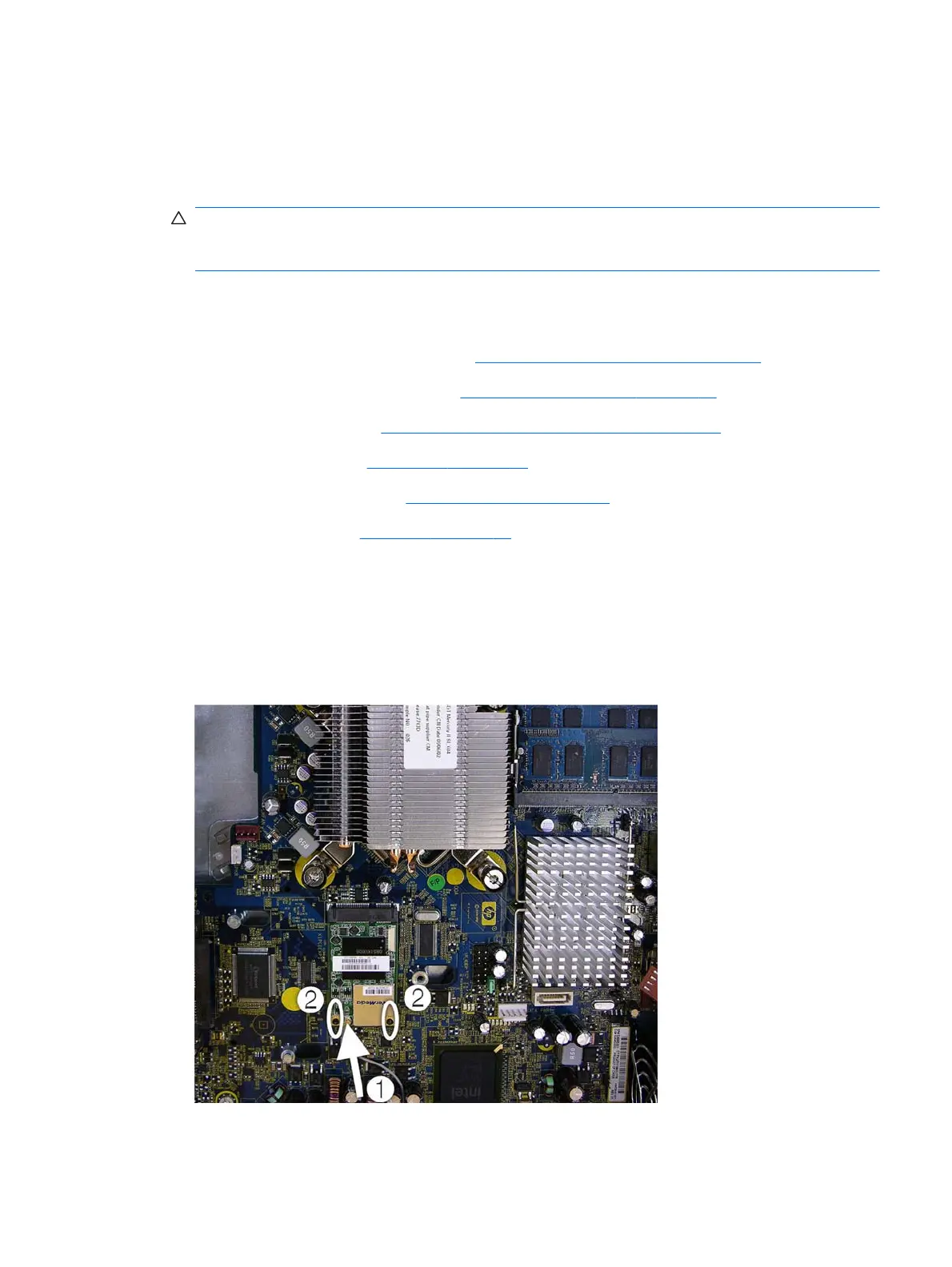
7. Disconnect the antenna cable from the connector on the TV tuner module.
8. Remove the two Torx T5 screws that secure the TV tuner module to the system board.
9. Lift the card to a 45 degree angle, and then remove the module from the connector by pulling it
away at an angle.
Figure 6-35 Removing the TV tuner module
TV Tuner Module
61