Cable Connections
System board connectors are color-coded to make it easier to find the proper connection.
System Board Connections
System Board Connector Connector Name Connector Color Description
P9 CHFAN1 Maroon Front chassis fan
P11 CHFAN2 Brown Rear chassis fan
P6 SPRK White Internal speaker
P61 SATA1 White Optical data
P125 HSENSE White Hood sensor
P151 BOOST Black ReadyBoost module
P160 N/A Black Optical power
P160 N/A Black Optical power
Replacing the Optical Drive
The Ultra-Slim Desktop uses a slimline Serial ATA (SATA) optical drive.
Removing the Existing Optical Drive
1. Prepare the computer for disassembly (Preparation for Disassembly on page 178).
2. Remove the computer access panel (
Computer Access Panel on page 183).
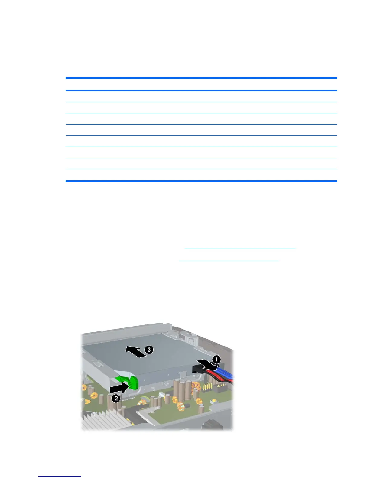
3. Disconnect the cable on the rear of the optical drive (1), push the green release latch on the right
rear side of the drive toward the center of the drive (2), then slide the drive forward and out of the
bay through the front bezel (3).
Figure 9-16 Removing the Optical Drive
Cable Connections 191
 Loading...