Chapter 6 Function Introduction Shenzhen Hpmont Technology Co., Ltd
―78― HD5L Series Controller User Manual
Code Name Description Range
factory setting
Note:
1
At up, up limit of No. 1 and No. 2 function is corresponding to 10V, while down limit is
corresponding to 5V;
2
At down, up limit of No. 1 and No. 2 function is corresponding to 0V, while down limit is
corresponding to 5V.
3: Output current (0-twice of controller rated current).
4: Output voltage (0-1.2 times of controller rated voltage).
5: DC bus voltage (0-2.2 times of controller rated voltage).
Note: Up limit of No. 3
5 functions is corresponding to max output voltage 10V.
6: AI1 input (0-10V).
7: AI2 input (-10-10V/0-20mA).
8: AI3 input (-10-10V/0-20mA).
9: AI4 input (-10-10V/0-20mA).
Note: When the negative voltage of No. 7
9 function is as input, the AO will output its
absolute value.
F13.19 AO1 gain 0.0
200.0
100.0%
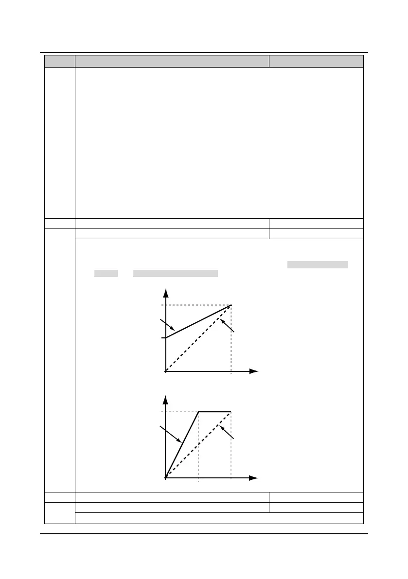
• This parameter is used to realise the proportional relation adjustment of AO1 analogue output.
• The formula is: Y=kX+b
• Y is actual output value, X is output value before being adjusted, k is analogue output gain
(F13.19), b is analogue output bias (F13.18).
The relationship between analogue output and bias is shown as following figure.
The relationship between analogue output and gain is shown as following figure.
F13.20 AO2 bias -100.0
100.0
0.0%
F13.21 AO2 gain 0.0
200.0
100.0%
Refer to parameters F13.18 and F13.19.
0
10
F13.18=0
F13.18=50%
50%
100%
Value after regulating (V)
Value before regulating (V)
0
10
100%
F13.19=100%
F13.19=200%
5
Value after regulating (V)
Value before regulating (V)

 Loading...