PVCHECKs-PRO
EN - 23
6.4. M – MEASUREMENT OF INSULATION ON PV MODULES/STRINGS/FIELDS
The purpose of this function is measuring the insulation resistance of the active conductors
of PV modules, strings and fields according to the prescriptions of standards
IEC/EN62446-1 and IEC/EN61557-2, with no need to use an external switch to short-
circuit the positive and negative terminals.
CAUTION
Insulation measurement can be performed on a single module, string or on
an installation consisting in more strings connected in parallel.
Separate the string/installation from the inverter and from possible
overvoltage protections.
If the module/string has a pole connected to earth, this connection must be
temporarily interrupted.
In compliance with standard IEC/EN62446-1, test voltage Vtest must be ≥
rated voltage of the installation.
Standard IEC/EN61557-2 sets 1M as a minimum value of insulation
resistance for installations with a rated voltage higher than 120V.
We recommend measuring insulation directly on the module/string/field
located upstream of possible blockin
diodes.
The instrument measures insulation in the following modes:
DUAL mode the instrument measures insulation in a sequence between the positive
pole (+) and the PE reference and between the negative pole (-) and the PE reference
of PV modules, strings or fields, and calculates overall resistance Rp.
TMR mode the instrument measures continuously (with a max duration of 999s)
between terminal “N” and the PE reference, displaying the minimum resistance value
obtained at the end of the selected time. In this way, the instrument also calculates the
DAR (Dielectric Absorption Ratio) and PI (Polarization Index) parameters, if the
duration of the test is suitable for these parameters’ calculation.
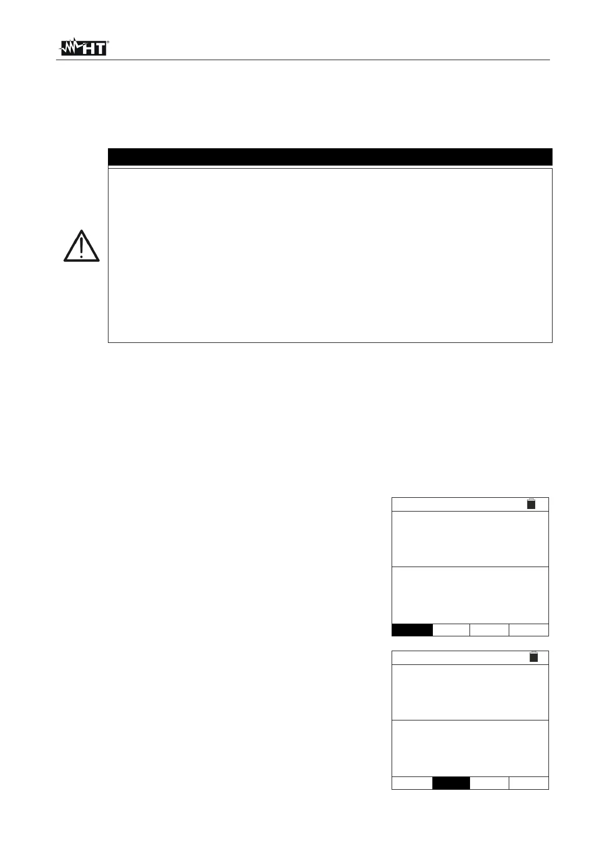
6.4.1. Measuring insulation – DUAL mode
1. Position the cursor onto M by using the arrow keys
(,) and confirm with ENTER. The display shows the
screen to the side. By using the arrow keys (,) again,
select the “DUAL” measuring mode, in position “MODE”.
M 15/10 – 18:04
(+) (-)
Vtest - - - - - - V
Riso - - - - - - M
Rp - - - M
VPN VPE VNE
0V 0V 0V
DUAL 1500V 1.00M
MODE Vtest. Lim.
2. Use the arrow keys or and select the position
“Vtest” to set the test voltage.
3. Use the arrow keys (,) to select one of the following
test voltages (Vnom): 250, 500, 1000, 1500VDC. Please
remember that, in compliance with standard IEC/EN
62446-1, test voltage Vtest must be ≥ rated voltage of the
installation.
M 15/10 – 18:04
(+) (-)
Vtest - - - - - - V
Riso - - - - - - M
Rp - - - M
VPN VPE VNE
0V 0V 0V
DUAL 1500V 1.00M
MODE Vtest. Lim.