PVCHECKs-PRO
EN - 18
6.3.2. Carrying out continuity measurements in Standard (STD) mode
1. Position the cursor onto RPE by using the arrow keys
(,) and confirm with ENTER. The display shows the
following screen. The symbol “STD” is shown on the
display.
RPE 15/10 – 18:04
R - - -
Itest - - - mA
STD 2.00 - - -
MODE Lim.
><
2. Use the arrow keys or and select the position “Lim.”.
The display shows the screen to the side.
3. Use the arrow keys (,) to set the limit reference
threshold for continuity measurement, which can be
selected in a range between 0.01 9.99 in steps of
0.01 (please remember that standard IEC/EN62446-1
does not establish a limit value for resistance and typical
values are approx. 1 or 2).
RPE 15/10 – 18:04
R - - -
Itest - - - mA
STD 2.00 - - -
MODE Lim.
><
4. Carry out the initial calibration of the measuring cables (see § 6.3.1).
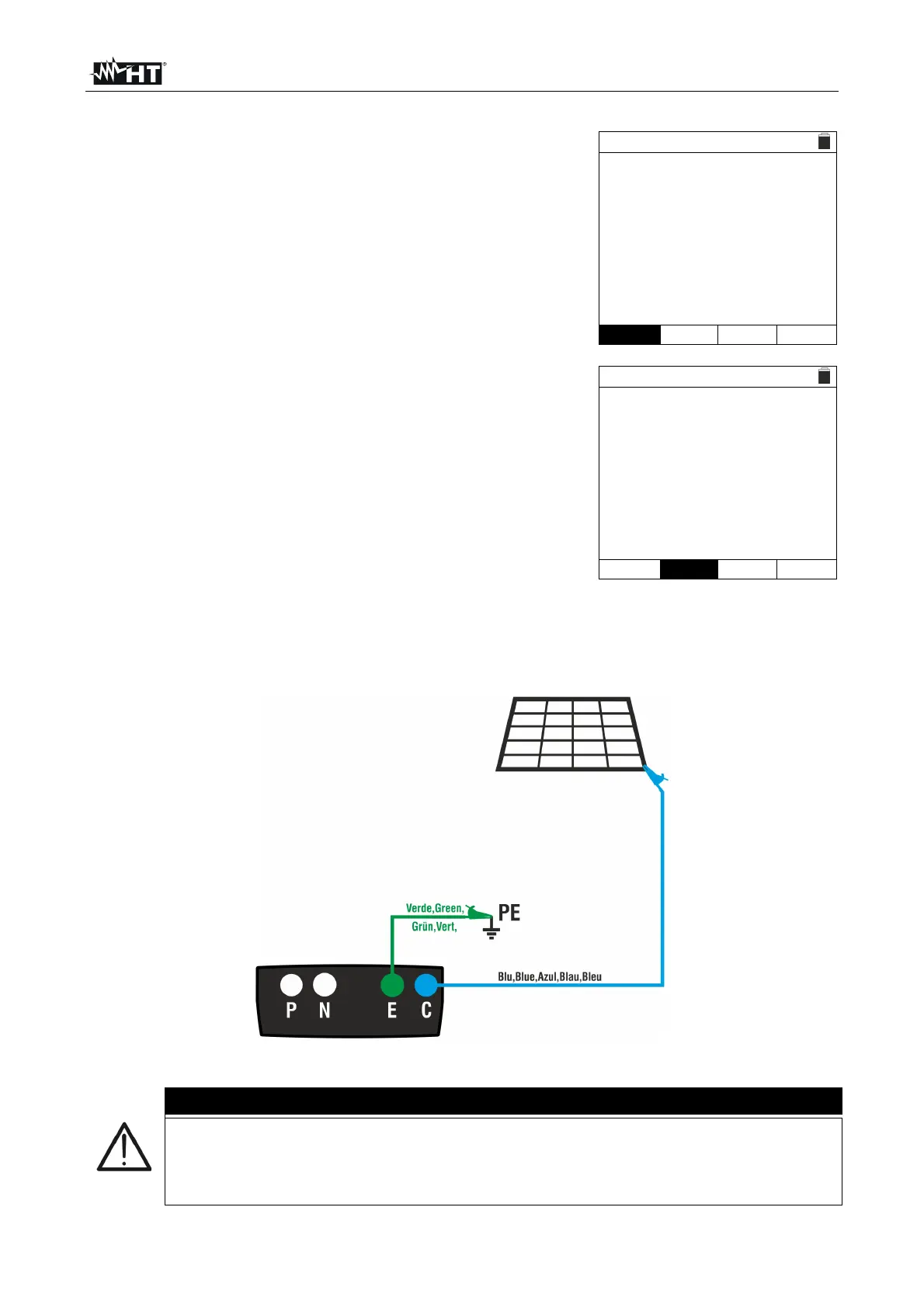
5. Connect the instrument to the PV module/string being tested and to the main earth
node of the system as shown in Fig. 6.
Fig. 6: Connection of instrument for continuity measurement on structures of the PV
installation
CAUTION
Upon pressing the GO/STOP key, different error messages can be displayed by
the instrument (§ 6.3.4) and, therefore, the test cannot be started. Check and
eliminate, if possible, the problem causing the error message before going on
with the test.