PVCHECKs-PRO
EN - 26
4. Use the arrow keys or and select the position “Lim.”.
The display shows the screen to the side.
5. Use the arrow keys (,) to set the minimum limit
threshold for insulation measurement, which can be
selected among the values 0.05, 0.10, 0.23, 0.25, 0.50,
1.00, 50M. Please remember that standard IEC/
EN62446-1 sets 1M as a minimum value of insulation
resistance for installations with a rated voltage higher
than 120V.
M 15/10 – 18:04
Vtest(-) - - - V
Ri(-) - - - M
Time - - - s
DAR - - - PI - - -
VPN VPE VNE
0V 0V 0V
TMR 1500V 1.00M 3s
MODE Vtest. Lim. Time
6. Use the arrow keys or and select the position
“Time”. The display shows the screen to the side.
7. Use the arrow keys (,) to set the measuring time in
the range: 3s ÷ 999s
M 15/10 – 18:04
Vtest(-) - - - V
Ri(-) - - - M
Time - - - s
DAR - - - PI - - -
VPN VPE VNE
0V 0V 0V
TMR 1500V 1.00M 3s
MODE Vtest. Lim. Time
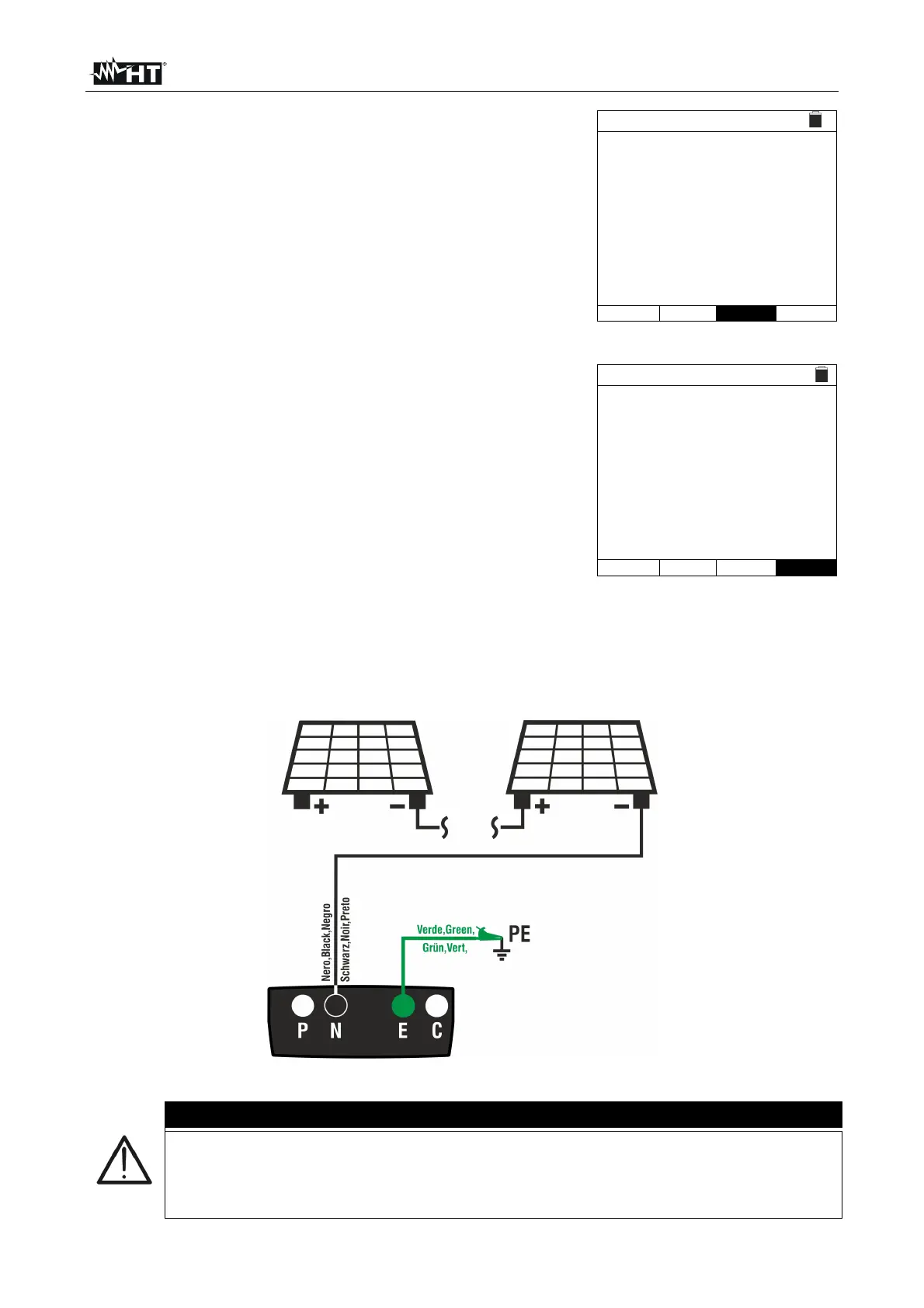
8. Connect the instrument to the PV string to be tested as shown in Fig. 8. The test can
be carried out also on more strings connected in parallel to each other. Please
remember that it is also necessary to separate possible overvoltage protections
connected to the cables of the string(s) and that it is recommended to measure
upstream of possible blocking diodes.
Fig. 8: Instrument connection for insulation measurement in TMR mode
CAUTION
Upon pressing the GO/STOP key, different error messages can be displayed by
the instrument (§ 6.4.3) and, therefore, the test cannot be started. Check and
eliminate, if possible, the problem causing the error message before going on
with the test.