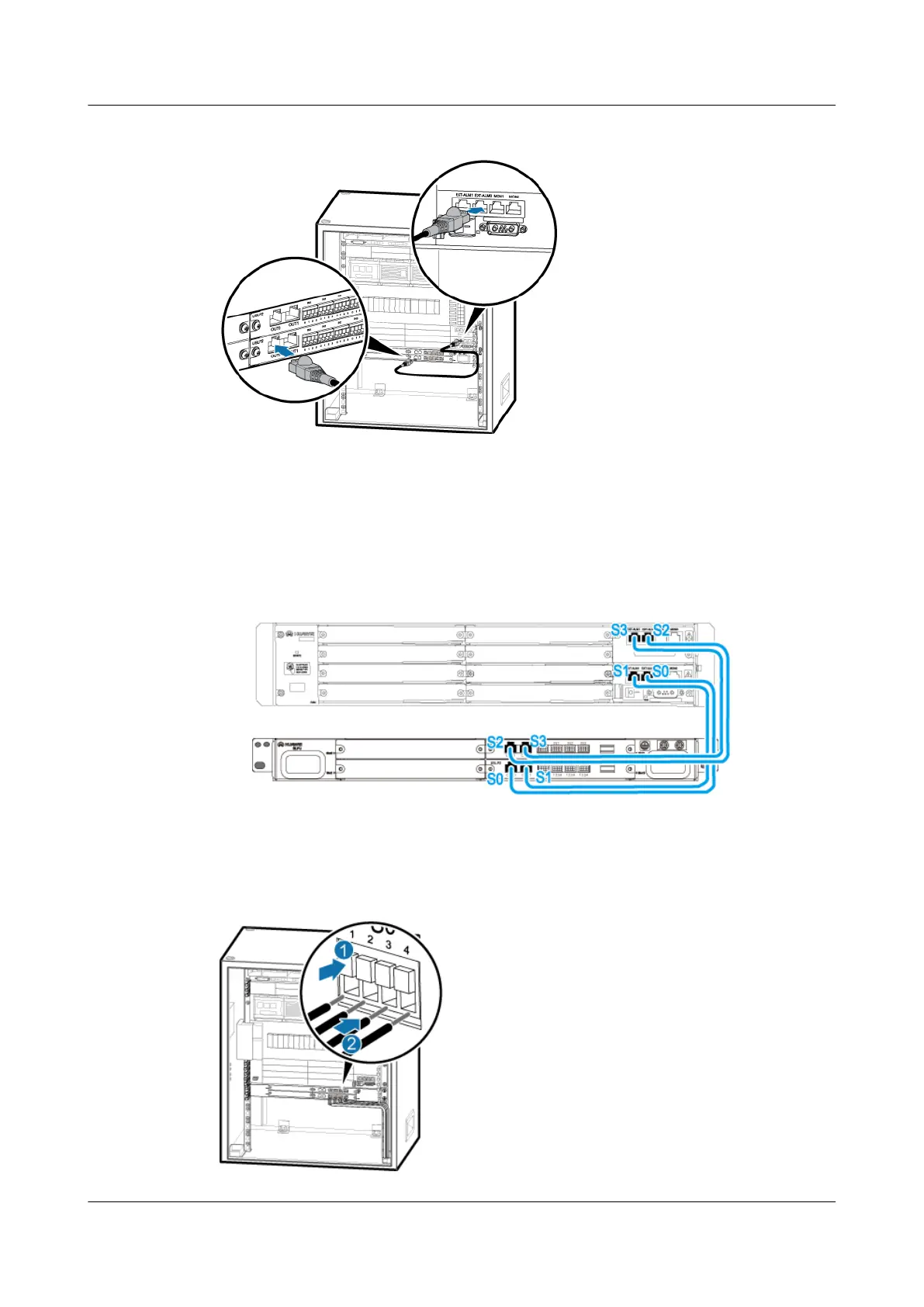
Figure 8-45 Installing the surge protection transfer cable for monitoring signals
1. Connect one end of the cable to the OUT0 port on the USLP2 in slot 3 of the SLPU.
2. Connect the other end of the cable to the EXT_ALM0 port on the UPEU in the BBU.
3. Connect the other three surge protection transfer cables for monitoring signals by referring
to Figure 8-46.
Figure 8-46 Connections of surge protection cables for monitoring signals
Step 4 Install the external dry-contact monitoring signal cables, as shown in Figure 8-47.
Figure 8-47 External dry-contact monitoring signal cables
DBS3900 (Ver.B)
Installation Guide
8 Outdoor Scenario with DC Power Supply (BBU Installed
in a +24 V DC APM30H)
Issue 06 (2011-09-15) Huawei Proprietary and Confidential
Copyright © Huawei Technologies Co., Ltd.
250