2. Lead the other end through the cable outlet module on the right at the bottom of the OMB,
and then route the cable to external power equipment. For details about how to install a
cable outlet module, see 9.4.2 Installing a Cable Outlet Module in an OMB.
Step 2 Route the cable by referring to 9.4.1 Cabling Requirements, and then use cable ties to bind the
cable.
Step 3 Label the installed cables. For details, see Attaching a Cable-Tying Label.
Step 4 Run each cable that leaves the cabinet in the PVC corrugated pipe, and then tie the pipe to the
cable hole in the cabinet.
Step 5 Waterproof the connector.
----End
Installing a BBU Power Cable
A BBU power cable feeds power into the BBU from the DCDU-03B when a DBS3900 works
in DC power supply scenario.
Context
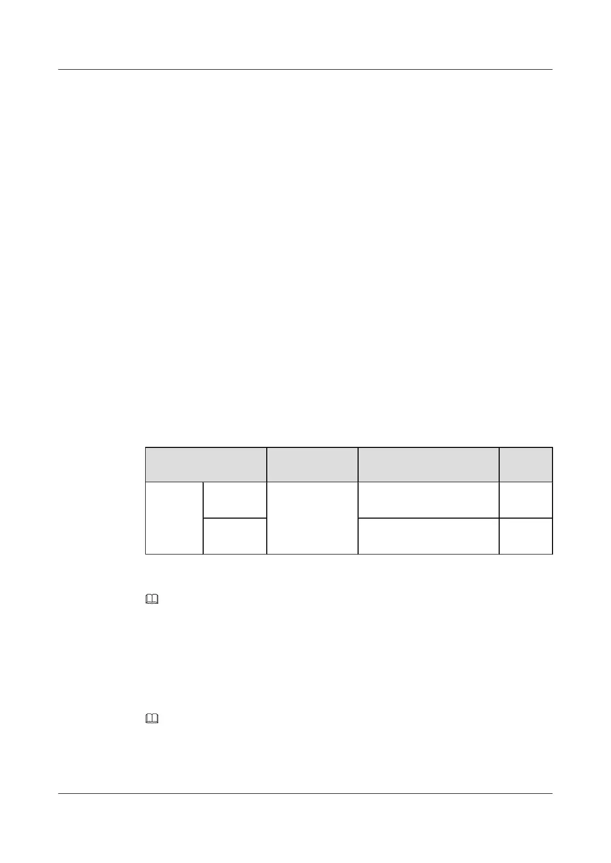
Table 9-3 lists the specifications of a BBU power cable when a DCDU-03B supplies power.
For details about a BBU power cable, see BBU Power Cable (OMB).
Table 9-3 Specifications of a BBU power cable
Cable
One End The Other End Descript
ion
BBU
power
cable
RTN(+)
wire
3V3 power
connector
OT terminals bent by 90° (M4,
6 mm
2
)
Black
NEG(-)
wire
OT terminals bent by 90° (M4,
6 mm
2
)
Blue
NOTE
The colors and structures of cables vary according to countries and areas. If the cables are purchased locally,
the colors and structures of the cables may be different.
Procedure
Step 1 Add OT terminals to a BBU power cable. For details, see Assembling the OT Terminal and the
Power Cable.
NOTE
A 3V3 power connector is added to one end of a BBU power cable, and you only need to add OT terminals
to the other end onsite.
Step 2 Install a BBU power cable, as shown in Figure 9-21.
DBS3900 (Ver.B)
Installation Guide
9 Outdoor Scenario with DC Power Supply (BBU Installed
in an OMB)
Issue 06 (2011-09-15) Huawei Proprietary and Confidential
Copyright © Huawei Technologies Co., Ltd.
306
 Loading...


