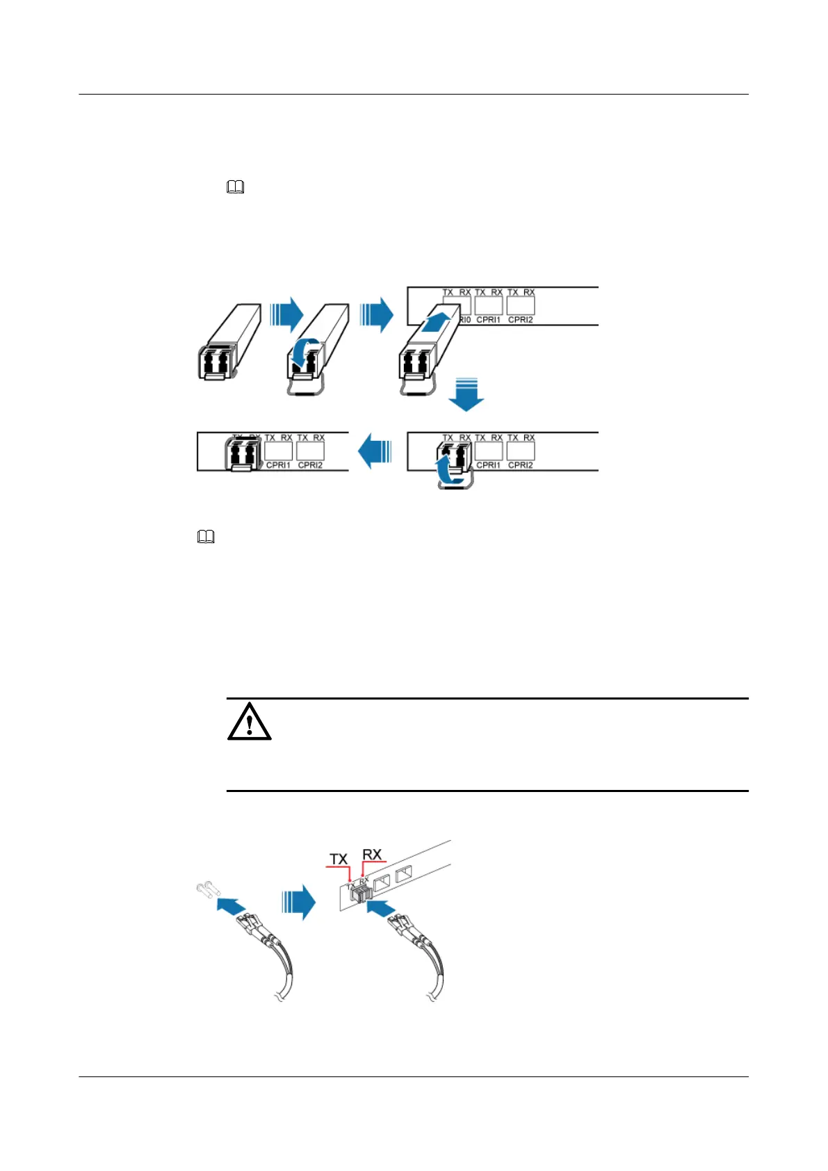
2. Insert the optical module into the CPRI port on the GTMU, WBBPb, WBBPd, or LBBP,
and then insert the optical module of the same type
(1)
into the CPRI_W or CPRI0 port on
an RRU.
NOTE
(1) The optical modules with the same label are of the same type.
3. Turn the puller on the optical module inwards.
Figure 11-25 Installing an optical module
Step 2 Install an CPRI optical cable, as shown in Figure 11-26.
NOTE
For details about the connections of the CPRI optical cables, see the BBU3900 Hardware DescriptionCPRI
Cable Connections.
1. Remove the dustproof caps from the connectors of the optical cable.
2. Insert the DLC connectors labeled 2A and 2B at one end of the CPRI optical cable into the
optical module on the GTMU, WBBPb, WBBPd, or LBBP, and then insert the DLC
connectors labeled 1A and 1B at the other end into the optical module on the RRU.
CAUTION
If both ends of the optical cable are the LC connectors, the TX and RX ports on the BBU
are respectively connected to the TX and RX ports on the RRU.
Figure 11-26 Installing a CPRI optical cable
Step 3 Route the CPRI optical cable along the left of the cabinet, and then lead it out of the cabinet
from the cable hole on the left of the bottom. For details, see 11.4.1 Cabling Requirements.
DBS3900 (Ver.B)
Installation Guide
11 Indoor Scenario with DC Power Supply (BBU Installed
on a Wall)
Issue 06 (2011-09-15) Huawei Proprietary and Confidential
Copyright © Huawei Technologies Co., Ltd.
394