Prerequisite
WARNING
Before soldering the connectors to the E1/T1 cable, ensure that both ends of the E1 cable are
disconnected from any devices. In addition, all the connectors are soldered to the E1 cable during
the same session.
Procedure
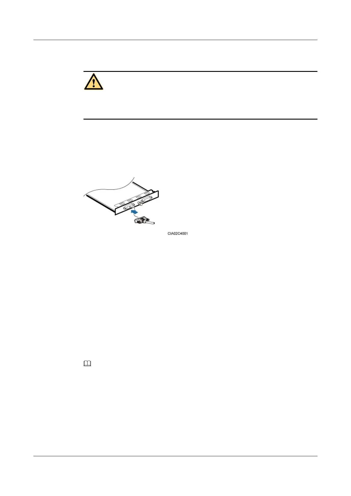
Step 1 Link the DB26 male connector of the E1/T1 cable to the port labeled E1/T1 on the UTRP,
GTMU, or WMPT, as shown in Figure 12-15.
Figure 12-15
Step 2 Route the cables by referring to 12.4.1 Cabling Requirements, and then use cable ties to bind
the cables.
Step 3 Label the installed cables by referring to Attaching an L-Shaped Label.
----End
Installing a FE/GE Cable
A FE/GE cable transmits baseband signals between a BBU and external transmission equipment
when a DBS3900 is deployed indoors.
Procedure
Step 1 Connect one end of a FE/GE cable to the port labeled FE0 on the GTMU or WMPT in a BBU,
as shown in Figure 12-16.
NOTE
You must use a shielded straight-through FE/GE cable.
DBS3900 (Ver.B)
Installation Guide
12 Indoor Scenario with DC Power Supply (BBU Installed in
a 19-Inch Rack)
Issue 06 (2011-09-15) Huawei Proprietary and Confidential
Copyright © Huawei Technologies Co., Ltd.
420
 Loading...


