Figure 12-17 Installing an optical module
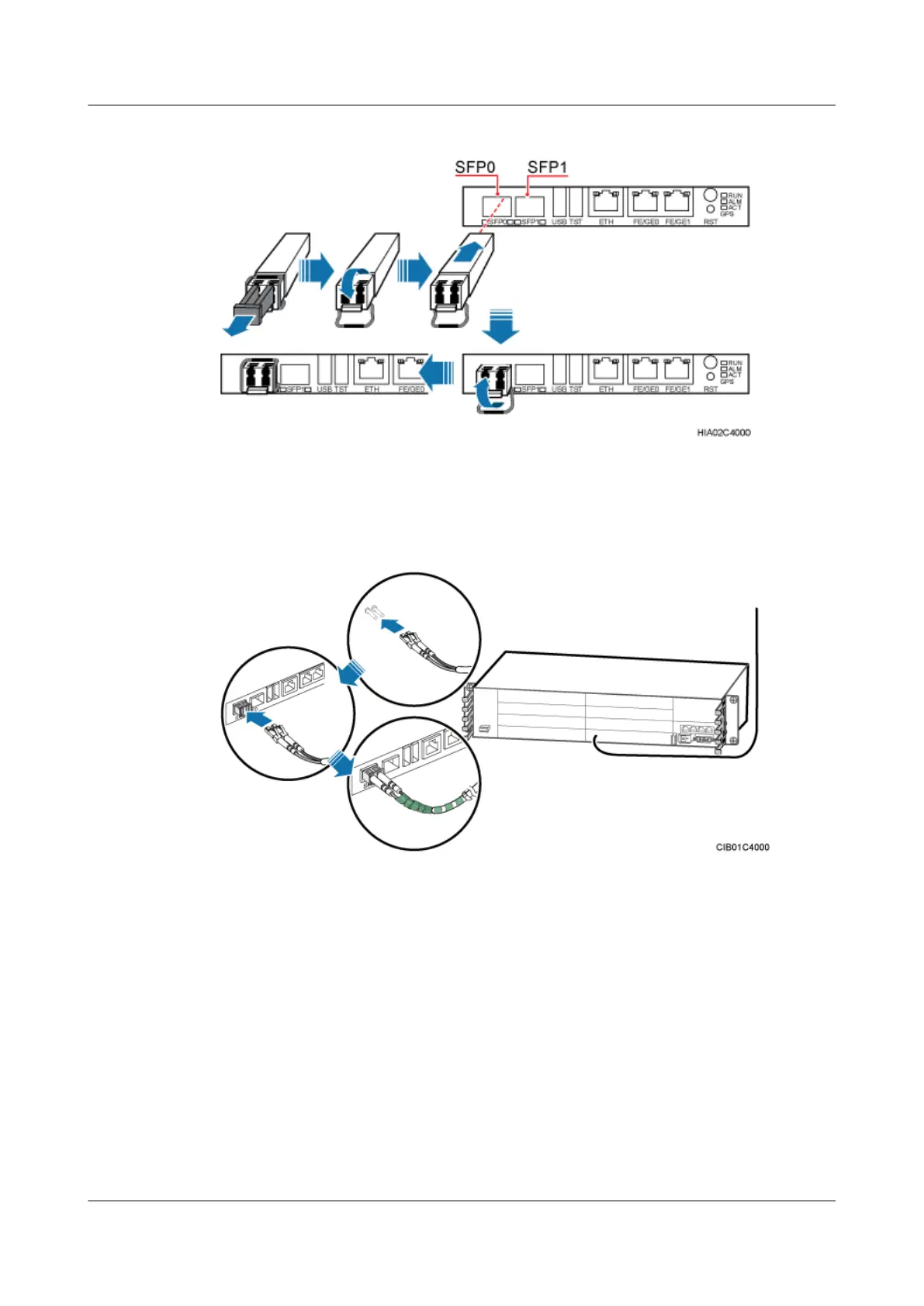
Step 2 Insert a FE/GE optical cable into the optical module, as shown in Figure 12-18.
Figure 12-18 Installing a FE/GE optical cable
Step 3 Route the FE/GE optical cable along the cable trough on the right of the cabinet, and then use
cable ties to bind the cable.
Step 4 Route the cable by referring to 12.4.1 Cabling Requirements.
Step 5 Attach labels on the optical cable. For details, see Attaching a Sign Plate Label.
Step 6 Coil the optical fiber with winding plastic tape at the end connected to the BBU. The tape is
coiled between the optical connector and the first cable tie on the cabinet, as shown in Figure
12-19.
DBS3900 (Ver.B)
Installation Guide
12 Indoor Scenario with DC Power Supply (BBU Installed in
a 19-Inch Rack)
Issue 06 (2011-09-15) Huawei Proprietary and Confidential
Copyright © Huawei Technologies Co., Ltd.
422