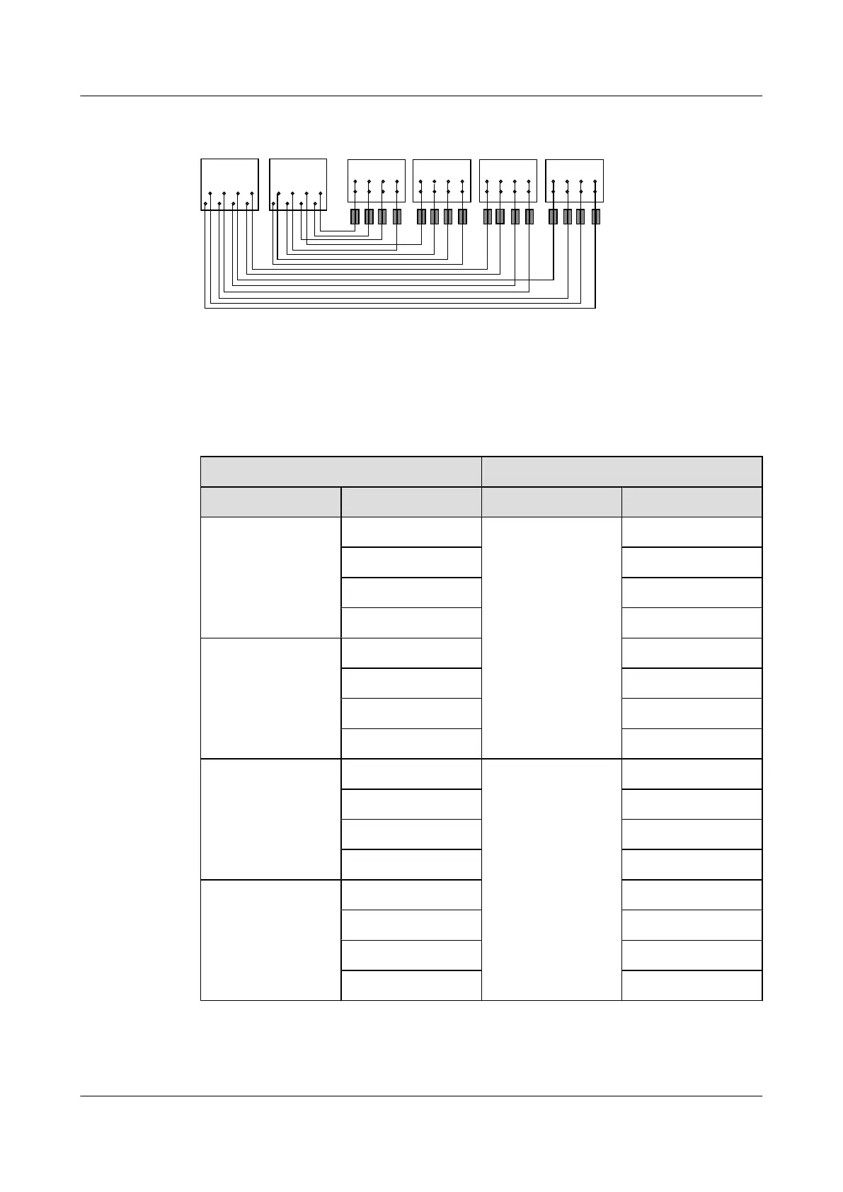
Figure 6-42 Mapping relationship between the pins in the input and output ports on the USLP2
1
2
3 4 1
2
3 4 1
2
3 4 1
2
3 4
8 6 4 2
7 5 3 1
8 6 4 2
7 5 3 1
IN0 IN1 IN2 IN3
OUT0 OUT1
Table 6-2 lists the mapping relationship between the pins in the input and output ports on the
USLP2.
Table 6-2 Mapping relationship between the pins in the input and output ports on the USLP2
Input Output
Label Pin Label Pin
IN0 IN0.1 OUT1 OUT1.1
IN0.2 OUT1.2
IN0.3 OUT1.4
IN0.4 OUT1.5
IN1 IN1.1 OUT1.3
IN1.2 OUT1.6
IN1.3 OUT1.7
IN1.4 OUT1.8
IN2 IN2.1 OUT0 OUT0.1
IN2.2 OUT0.2
IN2.3 OUT0.4
IN2.4 OUT0.5
IN3 IN3.1 OUT0.3
IN3.2 OUT0.6
IN3.3 OUT0.7
IN3.4 OUT0.8
Table 6-3 lists the SLPU-related cables.
DBS3900 (Ver.B)
Installation Guide
6 Outdoor Scenario with AC Power Supply (BBU Installed
in an APM30H)
Issue 06 (2011-09-15) Huawei Proprietary and Confidential
Copyright © Huawei Technologies Co., Ltd.
55