Description
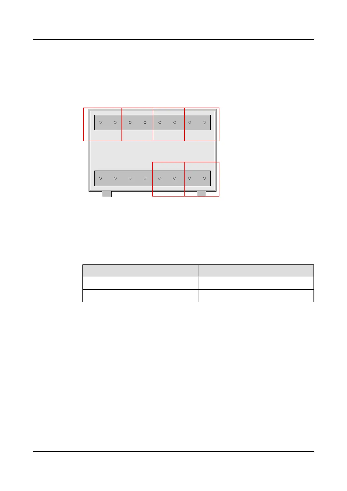
For the position of the monitoring port for relay node Boolean signals, see 2.2 Exterior of the
EMU. Figure 2-17 shows this port.
Figure 2-17 Monitoring Port for the relay node Boolean signals
RE1-RE2- RE1+RE2+
RE3-RE4- RE3+RE4+
NCNC NCNC RE5-RE6- RE5+RE6+
Table 2-12 lists the meanings of the terminals of the monitoring port for relay node Boolean
signals.
Table 2-12 Meanings of the terminals of the monitoring port for relay node Boolean signals
Silkscreen
Meaning
REi+ (i ranges from 1 to 6) Positive relay node output port i
REi- (i ranges from 1 to 6) Negative relay node output port i
Cable Connection
Figure 2-18 shows the cable connection of the relay node.
2 Overview of the EMU
EMU
User Guide
2-18 Huawei Proprietary and Confidential
Copyright © Huawei Technologies Co., Ltd.
Issue 13 (2009-12-30)