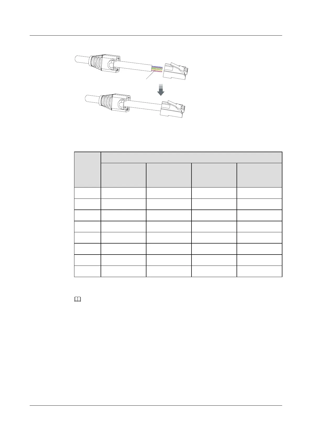
Figure A-13 Assigning the wires to the network cable
Wires arranged according to
the order of network cables
Table A-4 Wires assigned to the network cable
Wire Wire Color
Straight-
Through Cable
End A
Straight-
Through Cable
End B
Crossover
Cable End A
Crossover
Cable End B
1 White and orange White and orange White and orange White and green
2 Orange Orange Orange Green
3 White and green White and green White and green White and orange
4 Blue Blue Blue Blue
5 White and blue White and blue White and blue White and blue
6 Green Green Green Orange
7 White and brown White and brown White and brown White and brown
8 Brown Brown Brown Brown
NOTE
In Table A-4, end A and end B refer to both ends of a network cable.
Step 6 Use the crimp pliers to crimp the connector. Ensure that the connector is put correctly in the
crimp pliers. After crimping, the metal cover on the connector must be lower than other area on
the connector.
Step 7 Use a network cable tester or a multimeter to test all wires, and ensure that the wires are connected
properly.
Step 8 Push the boot to cover the RJ45 connector, as shown in Figure A-14.
SmartAX MA5612 Multi-service Access Module
Maintenance Guide A Appendix
Issue 01 (2012-07-25) Huawei Proprietary and Confidential
Copyright © Huawei Technologies Co., Ltd.
277

 Loading...