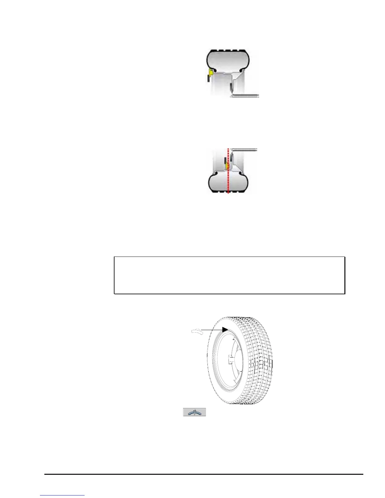
Use the inner Dataset
®
arm in the UPWARD position at the clip-on weight location to
measure the distance, diameter, and rim width dimensions. Refer to “Using the Auto
Dataset
®
Arms,” page 59.
Do NOT return the arm to the “home” position.
Using the DOWNWARD position, move the inner Dataset
®
arm disk edge to the
location for placement of the right edge of the adhesive weight on the right weight
plane and enter data by depressing the foot pedal. Refer to “Automatic Dataset®
Arms Operation,” page 59.
Close safety hood.
Press the green “START” button if “Hood Autostart” is disabled.
After wheel comes to a complete stop, raise safety hood.
The GSP9720JLR will find the TDC for the left weight plane if “Servo-Stop” is
enabled. “Servo-Stop” will hold the wheel in the TDC position while the weight is
applied.
NOTE: If optional HammerHead™ TCD weight locator is installed,
the weight should be applied at the location marked by the
laser. Refer to “3.23 Optional HammerHead™ TDC Laser
Adhesive Weight Locator,” on page 76.
Attach the clip-on weight amount shown on the LCD for the left weight plane to the
inner rim of the wheel.
If necessary, use the left to split the weight. Refer to “Split Weight
®
Feature,”
page 82.
Servo-Activated Laser automatically locates BDC to aid in fast adhesive weight
positioning.
GSP9720JLR Wheel Balancer Operation Instructions Balancing Procedures
53