INSTALLATION
6
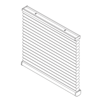
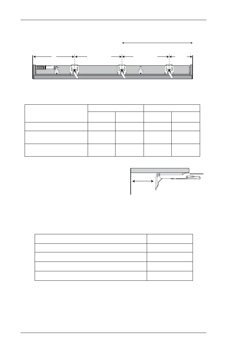
NOTE: Before the headrail is installed, the bracket levers need to be fully to the left.
Once the headrail is properly in place, the levers automatically click to the right.
■
The depth required for mounting will vary depending on the power supply and mounting
type.
■
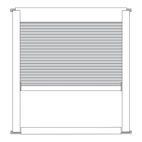
Center the installation brackets on
your marks and mark the location of
the screw holes.
➤
Allow sufficient rear clearance
when positioning the brackets.
NOTE: Rear clearance is the distance between the back of the installation bracket
and the glass or frame
➤
Add an extra
1
⁄
4
" of rear clearance if the optional back cover is used.
IMPORTANT: The back cover is not available with the rechargeable battery wand.
■
Use a level to check that the mounting surface is level. Shim (not provided) the brackets,
if necessary.
■
Use a
3
⁄
32
" drill bit to drill holes for the mounting screws.
CAUTION: Use drywall anchors when mounting into drywall.
18" Minimum for Battery Wand/
Rechargeable Battery Wand
Space Evenly
2" to 3"
7"
Jamb
Jamb
Space Evenly
Operating System Type
Minimum Mounting Depth Fully Recessed Depth
Without
Back Cover
With
Back Cover
Without
Back Cover
With
Back Cover
UltraGlide
®
1" 1
1
⁄
4
" 3
13
⁄
16
" 4
1
⁄
16
"
PowerView
®
Gen 3
with Battery Wand
2" 2
1
⁄
4
" 4
9
⁄
16
" 4
13
⁄
16"
PowerView Gen 3 with
Rechargeable Battery Wand
2
1
⁄
4
" — 4
13
⁄
16
" —
Rear
Clearance
Nearest
Operating System and Power Supply Rear Clearance
UltraGlide ¼"
PowerView Gen 3 with satellite battery ¼"
PowerView Gen 3 with battery wand ¾"
PowerView Gen 3 with rechargeable battery wand 1"