1199
Technical Description
A small amount of gain is applied to the incoming PPG signal to ensure that the Microcontroller
is functioning at its maximum resolution.
This signal is multiplexed with data relating to the infra red intensity.
Gain
The Tare line from the Microcontroller is sent to the PPG pod, this will reset the DC level at the
output from the probe and start the test.
This signal is also the control line for the multiplexer.
Tare
4.17 Obstetric Probe (OP2HS, OP3HS, D920-P, D930-P, FD1-P, FD3-P)
Tx
Xtal
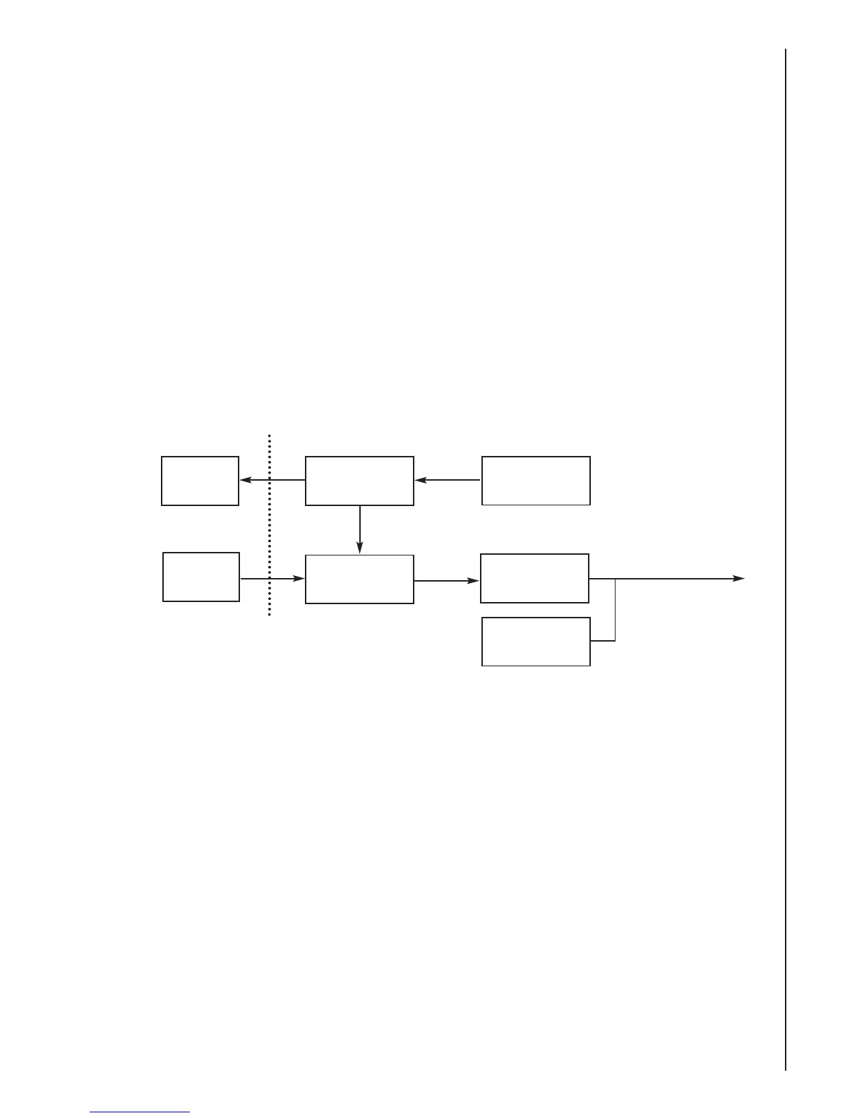
Block Diagram
Rx
Xtal
Transmitter
A ceramic resonator based oscillator circuit provides a reference for the probe receiver and, via
the transmitter, the output signal.
Oscillator
The output from the oscillator is amplified by a single transistor; the gain of this stage is
controlled by a variable resistor.
This allows the output voltage to be set according to the impedance of the probe head, thus
setting the output power level.
Transmitter
Demodulator
Oscillator
Amplifier
/
Filter
Probe
Coding
To
Control
Unit
Probe
Head
The demodulator effectively removes the carrier (transmitter frequency), which leaves us with a
Doppler shifted signal.
The demodulator stage requires a reference signal from the transmitter stage.
Demodulator
 Loading...