3333
Probe Head Replacement Procedure
2. Connect the head adaptor PCB (supplied with head alignment service kit) to the probe. Fit
the head to the adaptor PCB as shown below.
Gnd Tx
PPrroobbee
HHeeaadd
HHeeaadd
AAddaappttoorr
PPCCBB
PPCCBB
RReeff..
66AAHH118855
PPrroobbee
PPCCBB
3. Connect the probe in series with the DVM set to measure current and power supply (check
that voltage is 5V +/- 1%) as shown below, using power supply adaptor PCB(D920-P, D930-
P) and adaptor cable (OP/VP probe).
CAUTION
: Inccoorreecct
ccoonneecctiioon
wiillll
ddaamaagee
proobbee
eelleecctrooniiccs.
Gnd Rx
7.5 New Head Fitting and Alignment.
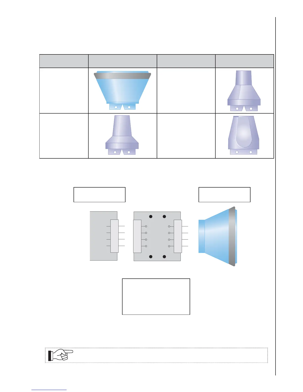
1. Select a new head of correct frequency, identified as shown below.
The probe heads are colour coded on the rear of the head as follows:
FREQUENCY HEAD
SHAPE FREQUENCY HEAD
SHAPE
2MHz
3MHz
8MHz
10MHz
4MHz
5MHz
EZ8
 Loading...