Do you have a question about the Huntleigh FD1-P and is the answer not in the manual?
Mandates precautions to avoid static damage to CMOS and microcontroller circuitry.
Details FHR calculation using amplitude envelope and auto-correlation of the Doppler audio signal.
Shows block diagram for obstetric probes and details Oscillator, Transmitter, Demodulator.
Shows block diagram for vascular probes and details Oscillator, Johnson Counter, Transmitter, Receive Amplifier.
Recommends dissipative mats, wrist straps, and anti-static bags to prevent ESD damage.
Provides step-by-step instructions for disassembling the control unit, including battery cover and case separation.
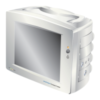
Details LCD and Loudspeaker replacement procedures.
Outlines steps for removing the Printed Circuit Board (PCB) from the control unit.
General guide for replacing sockets, switches, retractile cables, and volume controls.
Provides instructions for reassembling the control unit after servicing, including PCB, speaker, and switch fitting.
Covers replacing screws, battery cover, final testing, and refers to exploded view of D900-P.
Instructions for dismantling probe cases using a splitter for specific probe types.
Steps for dismantling D920-P, D930-P, and FD1-P probes, including clip removal and head disconnection.
Instructions for dismantling D920-P, D930-P, FD1-P, and FD3-P probes, including case moulding and screen tube removal.
Guides on selecting new probe heads, connecting to adaptor PCB, and initial power/current checks.
Details connecting scope probe to transmitter terminals and adjusting PR1 for sine wave output.
Shows head adaptor PCB references and vascular probe head assembly diagram.
Specific instructions for vascular probes on determining drive voltage and setting transmitter voltage.
Specific instructions for obstetric probes on adjusting PR1 for supply current and recording data.
Steps for reassembling probes, including sliding screen tube, soldering, and fitting case halves.
Instructions for reassembling D920-P, D930-P, FD1-P probes with silicon grease and head assembly.
Finishing steps for probe reassembly, including cleaning excess grease and fitting clips with adhesive.
Instructions for reassembling D920-P, D930-P, FD1-P, FD3-P probes with silicon and clips.
Final steps for probe reassembly, including securing clips, removing excess silicon, and allowing set time.
Procedure for waterproof testing of specific probe models using pressure and immersion.
Steps for testing vascular probes, including RFI checks, hiss levels, and bi-directional mode verification.
Instructions for testing obstetric probes, checking noise, signal levels, Fetal Mode, and audio performance.
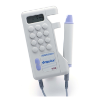
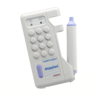
| Type | Doppler |
|---|---|
| Category | Medical Equipment |
| Probe Frequency | 2 MHz |
| Display | LCD |
| Power Supply | 9V battery |
| Output | Audio |