2200
Technical Description
The amplifier/filter amplifies the signal from the demodulator stage and removes unwanted
noise. The probe has a filter response tailored to maximise the output signal and minimise
noise and overload.
Amplifier/Filter
This superimposes a DC level (depending on probe frequency) onto the output signal.
Probe Coding
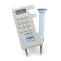
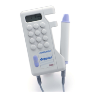
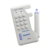
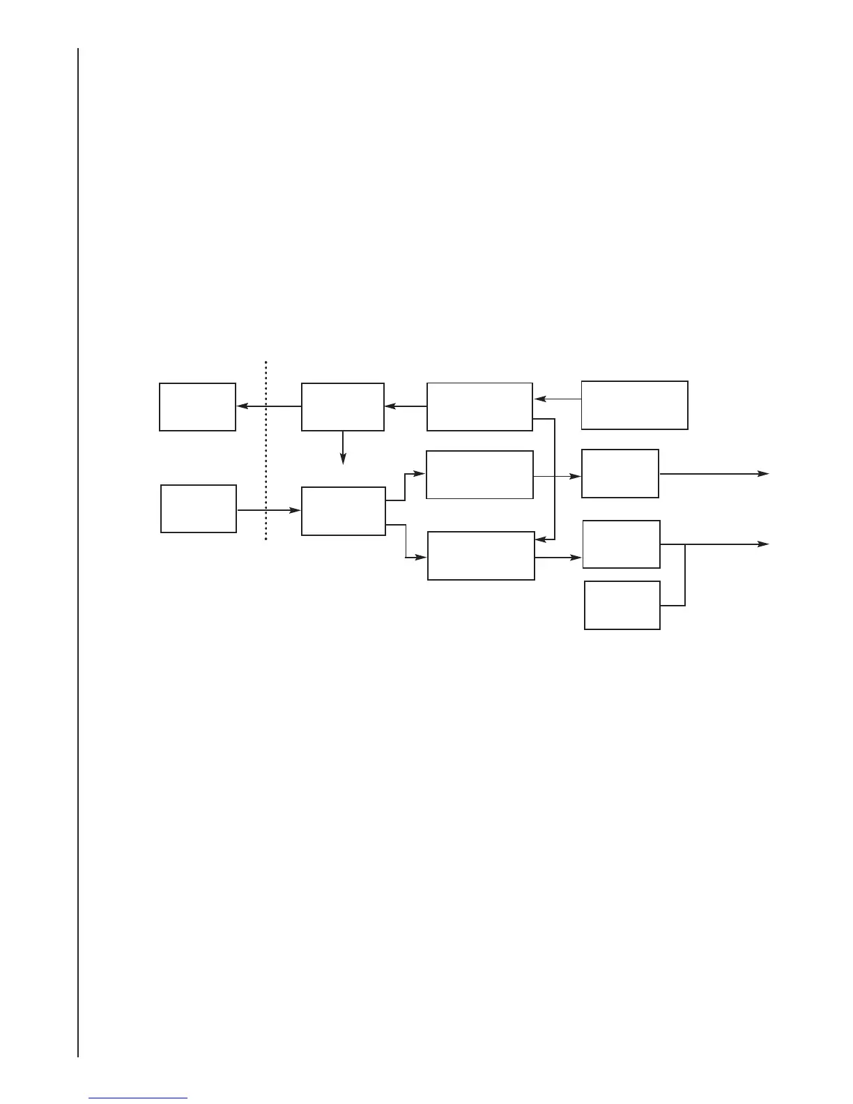
4.18 Vascular Probe (VP4HS, VP5HS, VP8HS, VP10HS, EZ8)
Tx
Xtal
Block Diagram
Rx Xtal
Transmit
Amplifier
A crystal oscillator provides references for the probe demodulator and output signal. The
oscillator frequency is four times that of the probe ultrasonic output.
Oscillator
Receive
Amplifier
Johnson
Counter
Amplifier
/
Filter
Probe
Coding
To
Control
Unit
Probe
Head
The Johnson Counter provides two outputs, which are 90° phase shifted with respect to each
other. It also divides the oscillator signal frequency by four.
Johnson Counter
The output from the oscillator is amplified by a single transistor; the gain of this stage is
controlled by a variable resistor.
This allows the output voltage to be set according to the impedance.
Transmitter
The received signal is amplified by two FETs (Cascode amplifier) providing the demodulators
with a suitable signal.
Receive Amplifier
Demodulator
Demodulator
Oscillator
Amplifier
/
Filter
 Loading...