2255
Servicing Procedures - Control Unit
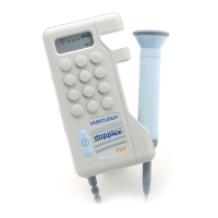
LCD Replacement (FD2-P, SD2-P, MD2-P, FD1-P, FD3-P, RD2)
1. Gently lift the display from its socket, noting the location of the orientation mark.
2. Fit the new display taking care to avoid stressing the display or bending the legs.
3. Remove protective film.
LCD Replacement (D920-P, D930-P, D900-P)
1. Cut off LCD legs, noting orientation and position in the socket (centred with spare hole at
each end).
2. Desolder and remove legs.
3. Fit new LCD (observing correct orientation and position) and solder legs.
4. Remove protective film
Loudspeaker Replacement
The loudspeaker wires may be unsoldered from the back of the loudspeaker after sliding the
sleeving from the terminals. Ensure that the sleeving is replaced on the new loudspeaker
terminals.
6.2 PCB Removal
1. First remove case halves as previously described.
2. Remove the on/off button and spring from the switch by lifting away.
The PCB is now free to be removed from the case, by pushing the battery terminals from inside
the battery compartment. Care should be taken not to damage the top panel label.
The PCB is located on three pillars, each having an "O" ring (see Fig 3) to ensure that the PCB
is located correctly. These rings are essential to prevent stressing the board. Take care not to
lose them.
The PCB is now freely accessible allowing replacement of electro-mechanical and leaded
components.
6.3 Changing Components
After dismantling the control unit as previously described the following repairs can be
undertaken.
Sockets/Switches
1. Carefully de-solder the component using solder wick. Do not use solder pumps as they
may generate static.
2. Ease the legs free in the board and lift the socket/switch free taking extreme care not to lift
or damage any tracking.
3. Clean the area around the component and fit the replacement.
4. Solder the component taking care not to overheat it or the PCB. Overheating the PCB could
result in the tracks breaking.
 Loading...