2211
Technical Description
The demodulators effectively remove the carrier (transmitter frequency), which leaves the
Doppler shifted signals.
They have two quadrature reference signals from the Johnson Counter stage.
Demodulators
The amplifier/filters amplify the signal from the demodulator stages and remove unwanted
noise. Each probe frequency has filters whose response is tailored to maximise the output
signal and minimise noise and overload.
Amplifier/Filters
This superimposes a DC level (depending on probe frequency) onto the output signal.
Probe Coding
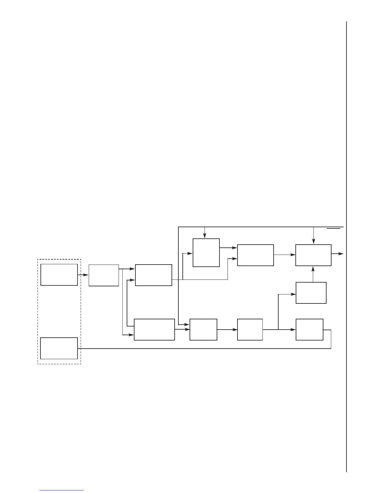
4.19 PPG Probe
Receiver
Block Diagram
Transmitter
Input
Amplifier
The Transducer comprises of a pair of a transmitter LED and receiver infra-red Photodiodes.
Transducer
Differential
Amplifier-11
Multiplexer
Amplifier
Counter
Tare
Transducer
This provides the necessary biasing from the receiving Photodiode and converts the current to
a dc voltage.
Input Amplifier
Window
Comparator
Sample
and
Hold
Emitter
Control
Differential
Amplifier-22
DAC
 Loading...