3311
Probe Head Replacement Procedure
7.3 Dismantling Procedure - (All probes except D920-P, D930-P, FD1-P,
& FD3-P)
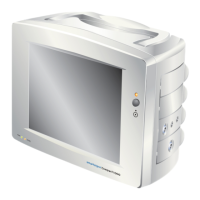
1. Align the case splitter jaws as shown below.
2. Gently squeeze the splitter handles together to release the case internal clips.
3. Remove the case splitter and separate the case halves from the probe assembly.
4. Carefully unplug the probe head.
5. De-solder the wire(s) from the screen tube and remove tube.
6. Clamp PCB lightly in vice along its length avoiding stress to the board.
Jaws engaged
in probe case
grooves
Splitting
the
Probe
Case
Plleeaasee
nootee:
Thhee
reetraacctiillee
ccaabbllee
must
bbee
ddiisccoonneeccteedd
froom
thhee
maaiin
uniit
bbeefooree
aa
hheeaadd
reepllaacceemeent
ccaan
bbeegiin.
(Seeee
seecctiioons
6.1
-
6.33).
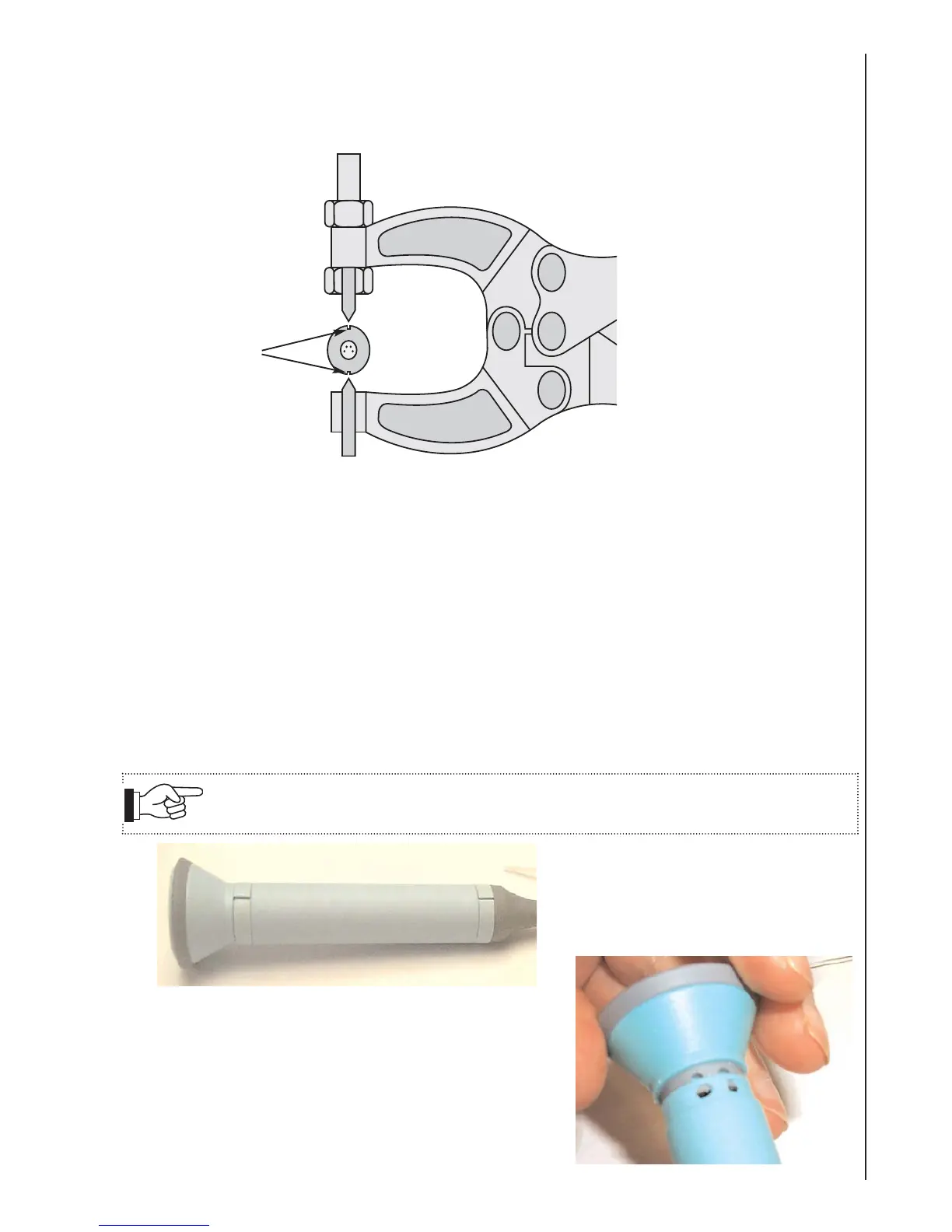
7.4a Dismantling Procedure - D920-P, D930-P & FD1-P
Remove the probe clips from the
probe with a firm leverage.
Discard clips.
1.
With the clips removed, take off the Head Assy by
disconnecting it from the 4 way connector on the
Probe PCB.
2.
 Loading...