2244
Servicing Procedures - Control Unit
6. Servicing Procedures - Control Unit
Due to the complexity of the product and the use of surface mount technology, the electronic
circuitry is not serviceable without specialised training and equipment.
The repairs detailed in this manual are therefore limited to replacement of certain parts in the
control unit, and replacement of probe heads only.
Fault finding is limited to checking for the presence or absence of signals around suspect
components using an oscilloscope or multimeter.
Repairs should only be undertaken by suitably skilled service personnel.
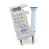
RD2 probe or sensor is not field serviceable as custom equipment is required during its
alignment.
CAUTIONS: Thhiis
eeqquiipmeent
ccoontaaiins
staatiicc
seensiitiivee
ddeeviiccees.
Reefeer
too
Appeenddiix
A
foor
reeccoommeenddeedd
aantii-sstaatiicc
hhaanddlliing
preeccaautiioons.
It
iis
eesseentiiaall
thhaat
thheesee
proocceeddurees,
oor
eeqquiivaalleent,
aaree
aaddoopteedd
too
aavooiidd
staatiicc
ddaamaagee
too
thhee
cciirccuiitry.
Duee
too
thhee
hhiighh
ddeens
iity
traacckkiing
aandd
smaallll
siizee
oof
ccoompooneents,
eextreemee
ccaaree
iin
hhaanddlliing
thhee
PCB
must
bbee
taakkeen
aat
aallll
tiimees.
WWhheen
soollddeeriing,
taakkee
ccaaree
too
eensuree
thhaat
thhee
miiniimum
hheeaat
i
is
aapplliieedd
too
thhee
bbooaardd
aandd
iits
ccoompooneents
foor
thhee
miiniimum
tiimee
neecceessaary
too
eensure
e
hhiighh
qquaalliity
jooiints.
Inspeecct
thhee
aareeaa
aarooundd
reepaaiirs
foor
soollddeer
spllaashhees
aandd
bbriiddgees.
Reefeer
too
aappeenddiix
A
foor
ddeetaaiills
oof
reeccoommeenddeedd
soollddeeriing
teecchhniiqquees.
6.1 Control Unit Dismantling Procedure (see figs 1,2,3)
1. Remove the battery cover by depressing and sliding down and away from the unit.
2. Lift the battery out.
3. Remove the 4 small screws from the rear case half. Do not remove the larger screw in the
top centre of the pocket clip.
4. Invert the unit and carefully separate the two case halves by hinging them apart from the
base up, freeing the cable grommet from the case as necessary. Pay special attention to
the labels on the side and top edges of the unit which adhere to both case halves.
Take care not to damage the locating lugs holding the top of the case halves together.
The PCB is now visible and the following components may be replaced without any further
dismantling:
• Loudspeaker
• LCD
 Loading...