3377
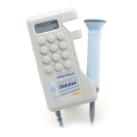
Probe Head Replacement Procedure
Plleeaasee
nootee:
Reemoovee
thhee
proobbee
hheeaadd
froom
thhee
PCB
iif
fiitteedd.
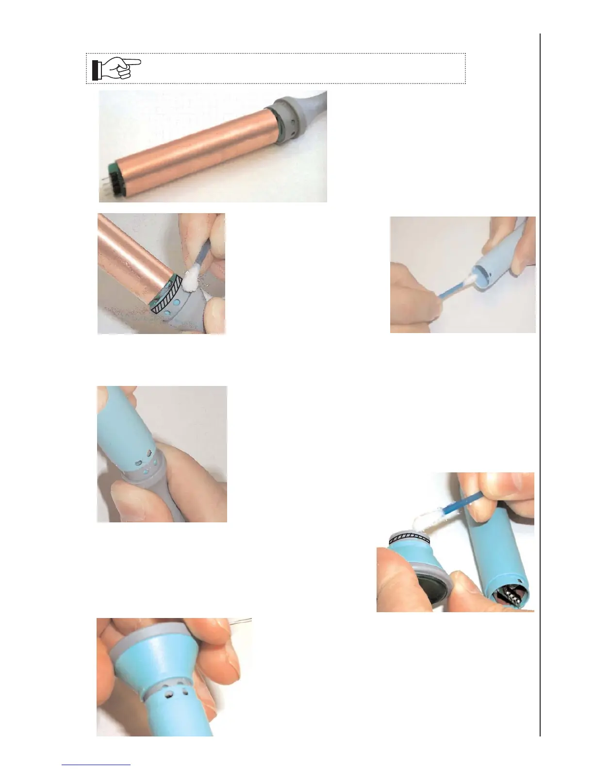
7.7a Reassembly Procedure - D920-P, D930-P & FD1-P
Slide the copper screen over the probe
and position so that the internal fold is
located against the edge of the PCB.
Re-solder in place using tinned copper
wire.
1.
Before applying silicon grease
to the End Cap, ensure there is
no residue of glue left behind
from the previous clips.
Ensure locating holes are
clean.
Apply silicon grease to the End
Cap and inside the case
moulding at both ends, using a
cotton bud as shown.
Applly
greeaasee
too
hhaatcchheedd
aareeaa
oonlly.
Avooiidd
llooccaatiing
hhoollees
oof
Endd
Caap.
2.
Slide the case moulding over the probe, ensuring that the
holes are fully aligned.
Remove any excess silicon grease with a dry tissue.
3.
Apply silicon grease to the head assembly, as shown by
the hatched area.
Ensure that the 4-way connector on the PCB is sitting
flush with the board, and that no pins are bent or
damaged.
4.
Attach Head Assembly to Probe Assembly.
Ensure that the PCB fits into the slot and the holes are
aligned.
Onlly
usee
thhee
siiddee
oof
thhee
Heeaadd
too
preess
ddoown.
Ensure the pins of the PCB locate into the Head PCB
socket.
5.
 Loading...