3322
Probe Head Replacement Procedure
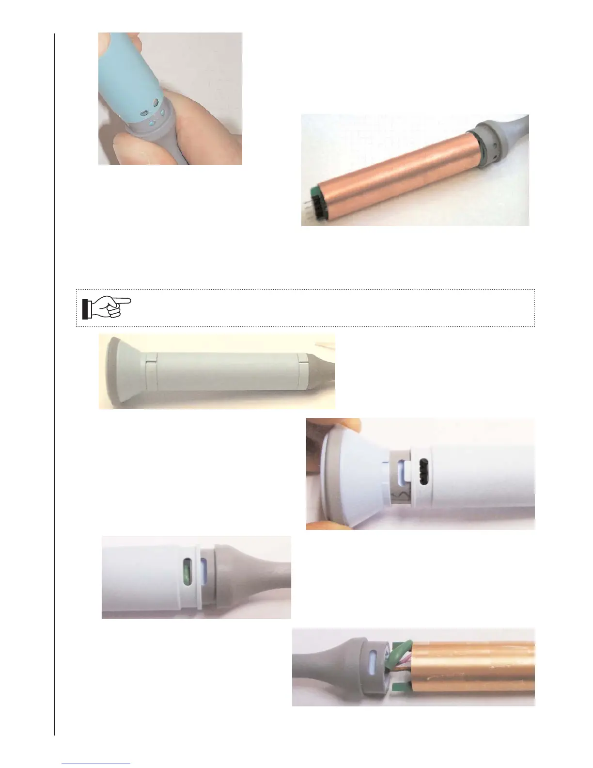
Detach the case moulding from the end cap and slide
case moulding over the probe.
Discard the case moulding.
3.
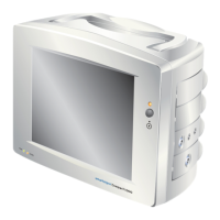
De-solder the wire from the copper
screen tube.
Remove the tube.
4.
Refer to section 7.5 of the head fitting and alignment section of this service manual.
Plleeaasee
nootee:
Thhee
reetraacctiillee
ccaabbllee
must
bbee
ddiisccoonneeccteedd
froom
thhee
maaiin
uniit
bbeefooree
aa
hheeaadd
reepllaacceemeent
ccaan
bbeegiin.
(Seeee
seecctiioons
6.1
-
6.33).
7.4b Dismantling Procedure - D920-P, D930-P, FD1-P & FD3-P
Remove the probe clips from the
probe with a firm leverage.
Discard clips.
1.
With the clips removed, take off the
Head Assy by disconnecting it from the
4 way connector on the Probe PCB.
2.
Detach the case moulding from the end cap
and slide case moulding over the probe.
Discard the case moulding.
3.
De-solder the wire from the copper
screen tube.
Remove the tube.
4.
Refer to section 7.5 of the head fitting and alignment section of this service manual.
 Loading...