4422
Probe Functional Test Specification
8. Probe Functional Test Specification
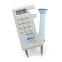
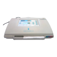
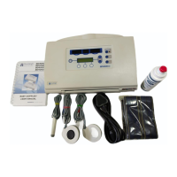
• Standard MD2-P (not required for D920-P, D930-P, FD1-P, FD3-P).
• Battery 9V alkaline manganese (6LF22, 6LR61) e.g. MN1604 or equivalent.
• Chart Recorder (not required for D920-P, D930-P, FD1-P, FD3-P, OP2HS or OP3HS). Refer to
Appendix D for specification.
• Recorder Lead (not required for D920-P, D930-P, FD1-P, FD3-P, OP2HS or OP3HS). Part
number 6AH073.
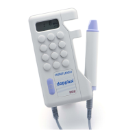
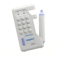
• Standard Probes as required
IMPORTANT:
Thhiis
teest
must
aallwaays
bbee
peerfoormeedd
aafteer
aany
seerviiccee
woorkk
hhaas
bbeeeen
unddeertaakkeen
oon
aany
proobbee.
Teest
reesullts
shhooulldd
bbee
reeccoorddeedd
oon
Deeviiccee
Hiistoory
Shheeeet
(Appeenddiix
B).
8.1 Equipment Required
1. Connect the probe to the test unit. Check that the chart recorder lead is plugged into the
unit's waveform output socket and that the recorder is switched on.
2. With the unit switched on and with a dry faceplate listen for any RFI (Radio Frequency
Interference) whilst handling the probe. This shows up as whines or whistles.
3. Background hiss levels should not be greater than the standard probes.
4. Check for crackling or intermittent audio when probe/retractile are moved.
This may indicate a loose connection.
5. Evaluate the performance level of the probe by testing on the body. Refer to standard
probe during test. See figure opposite for recommended probe testing sites.
6. Check that the control unit defaults to bi-directional mode. A probe symbol will be
displayed on the right hand side of the screen. Obtain signal and note direction and velocity
of blood flow, there should be no or very little cross-talk.
7. Obtain a test trace, refer to examples of traces in Appendix G.
8.2 Functional Tests - Vascular Probes VP4HS - VP10HS & EZ8
 Loading...