3344
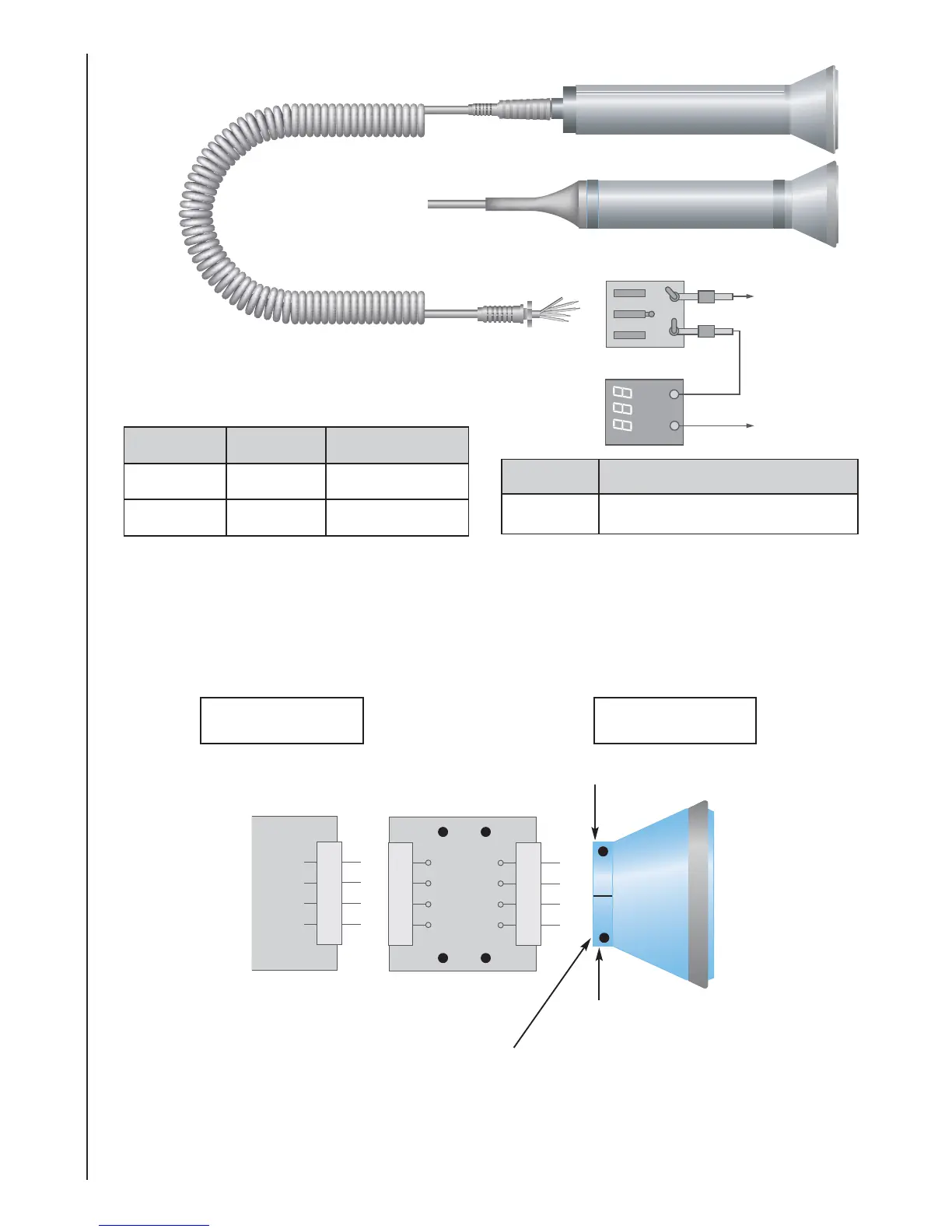
Probe Head Replacement Procedure
Power
Supply
Wiring
+Ve Output -VVe
Red White Black/Screen
Orange Violet Pink/Screen
Part
No. Description
6AH072 Head Alignment Service Kit
4. Switch on power supply.
5. Connect scope probe to the Transmitter Terminals (Tx) of the head adaptor PCB and
observe Sine wave.
6. Adjust PR1 to obtain 1.5V +/- 0.5Vpp (see Figure 3).
Gnd Tx
PPrroobbee
HHeeaaddPPrroobbee
PPCCBB
Gnd Rx
Tx
Rx
Date
Code
on
reverse
Figure
1
:Obstetric
Probe
Head
Assembly
Rx
Head
Impedence
Tx
Head
Impedence
 Loading...