6 Interface Between CNC And PLC
6 - 27
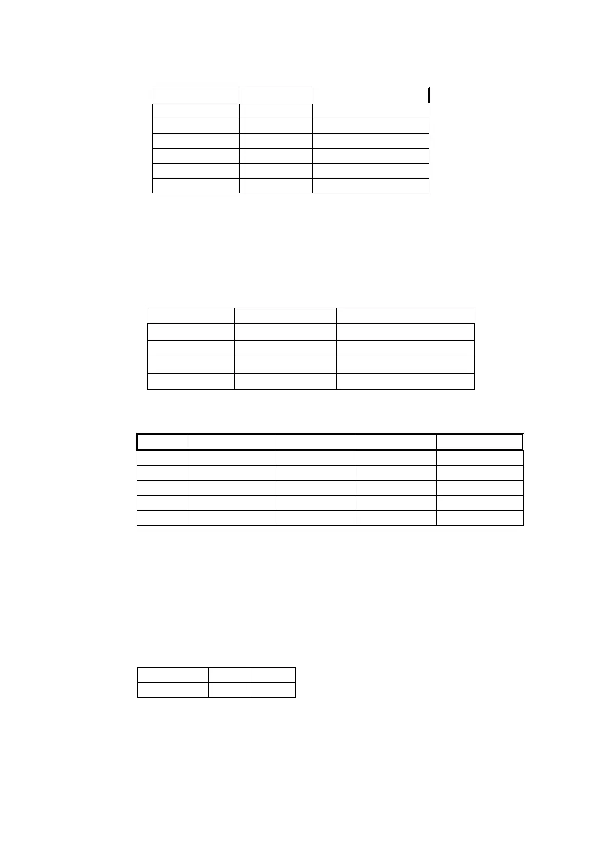
C-bit R228 Work Coordinate
C123 = 0→1
0 G54
C123 = 0→1
1 G55
C123 = 0→1
2 G56
C123 = 0→1
3 G57
C123 = 0→1
4 G58
C123 = 0→1
5 G59
Note that the work coordinate returns to G54 system whenever you press RESET
both in part program or PLC program.
R229, Setting the number of decimals for display after power on
Default = 3, range = 1 ~ 4.
R229 Format Number of Decimals
01
6∕1
1
02
5∕2
2
03
4∕3
3
04
3∕4
4
Example:
INPUT 3/4 Format 4/3 Format 5/2 Format 6/1 Format
X2 X0.0002 mm X0.002 mm X0.02 mm X0.2 mm
Y250 Y0.0250 mm Y0.250 mm Y2.50 mm Y25.0 mm
U2500 U0.2500 mm U2.500 mm U25.00 mm U250.0 mm
V25. V25.0000 mm V25.000 mm V25.00 mm V25.0 mm
F300 F300 mm/min F300 mm/min F300 mm/min F300 mm/min
R230, Page number for Man Machine Interface (MMI) display
Default = 01, range = 1 ~ 255.
R232, For selecting the axis in JOG and HOME mode to be drivable
When in JOG or HOME mode, use R232 to select the axis to be drivable as
follows.
BIT 1 0
Chose Axis Y X
When R232 = 1 → Bit 1=0 & Bit 0=1, X-axis is drivable.
When R232 = 2 → Bit 1=1 & Bit 0=0, Y-axis is drivable.
When R232 = 3 → Bit 1=1 & Bit 0=1, both X and Y-axis are drivable.