12 43576
51324 76
4321
1
A
432
A
B
C
D
B
C
D
Interface
CNC
(Customer Supplied)
041909
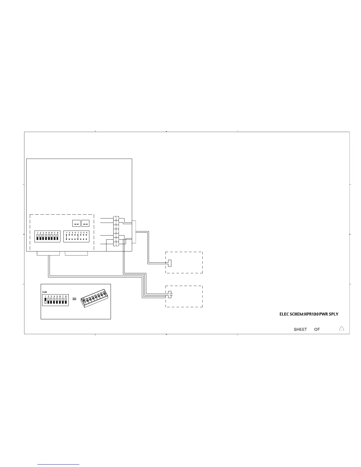
CONTROL BOARD
S100
J303
J300A J300B
Serial ID
Dipswitch Jumper Block
Machine Motion
Machine Interface I/O Cable
7
RED/BLK
RED
WHT
RED
Gas Console
078170
PS/Gas Power Cable
Customer Supplied
Remote On/Off
J106
2121
J107
Optional Remote On/Off
TB2
WHT
RED
RED/BLK
RED
6
2
1
1X1
Notes:
1) For single system installation set Serial ID (S100), Machine
Motion (J303), J106 & J107 as shown.
Relocate the white wire on TB2 from position #3 to position
#2. Connect customer supplied Remote On/Off cable in series
with the power supply and the gas console power switch.
Connect one terminal of the Remote On/Off cable to position
#2 on TB2 and the other terminal to position #3.
Refer to page 3 of the wiring diagram
Depress the Gas Console Power switch to the closed position (on position).
2) For a multi-system installation set up as described above, set jumpers as shown on the
multi-system interface page
3) The CNC will need a dedicated I/O for each system using the Remote On/Off feature
(contact should be rated for min. 24Vac, 0.5 Amp)
HPR PAC
Dry Cutting System
17
16
013348
K
Dipswitch setting example:
Switch 1 is in the ON position.
Switches 2-8 are in the OFF position.
 Loading...


