CENTER LOOP
INNER ARMING LOOP
OUTER ARMING LOOP
(OALD)
FREE EXIT LOOP
(optional)
A
B
C
E
F
D
PEDESTRIAN GATE & WALKWAY
C
(IALD)
To sequence the gates, set the
Installer Menu item, SG to “2” in
both gate operators.*
2
Operator & Loops**
Astrafccontrolandsecuritygates
are separated farther apart, Center
Loop moves toward centering under
theTrafcControlGate.
(OALD for both operators)
Loop can be offset from
C/L of barrier arm 1 to 5 ft
(31 to 152 cm)
(IALD for both operators)
SECURITY SLIDE GATE
TRAFFIC CONTROL GATE
IALDforTrafcControlGate
or Free Exit for both operators.
If loop used as Free Exit, you
must have an OALD loop.
Minimum 2 ft (61 cm)
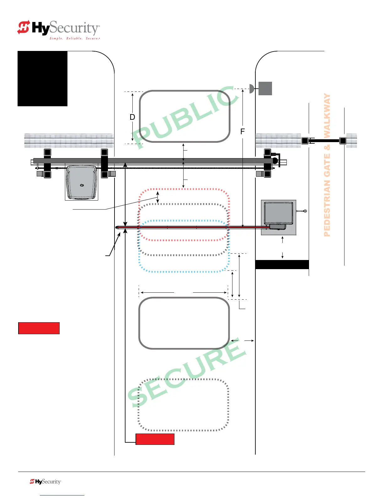
Sequenced Gates #2: Loop Layout
StrongArmPark DC with SlideSmart DC
Drawings not to scale.
*NOTICE
For sequenced gates to operate
properly, all vehicle detectors
must be wired to the Trafc
Control Gate.
If a communication failure occurs,
an AL22 (Alert 22) appears and the
buzzersounds.TheTrafcControl
Gate maintains functionality while-
the Security Gate defaults to open
until communication is restored
(or the Security Gate is manually
closed).
**NOTICE
Center to center between gates:
4 ft minimum (122 cm)
9 ft maximum (274 cm)
StrongArmParkDC Loop Layout
7-6 StrongArm M30/M50: Programming & Operations Manual www.hysecurity.com © 2014
Uni- or Bi-directional Trafc Control
Vehicles must pass from one loop to
the next without loss of detection.
Dimension “A” = 6 ft minimum to 12 ft
maximum (183 to 366 cm).
Dimension “B” = 2 ft minimum to 3 ft
maximum (61 to 91 cm).
Dimension “C” = 3 ft min. to 4 ft max.
Distance from edge of Center Loop to
C/L of the Security Gate is 3 to 4 ft.
Dimension “D” = 6 ft (183 cm).
Dimension “E” =
4 ft min. to 8 ft (122 to
244 cm)
max. Center Loop can be offset
from C/L of gate: 1 to 5 ft (31 to 152 cm).
Dimension “F” =
10 to 15 feet (3 to 3.6 m)
Optional access control
devices (card reader, etc.).
Align along 6 ft edge of the
Outside Obstruction Loop.
Location changes depending on
uni- or bi-directional trafc.
 Loading...