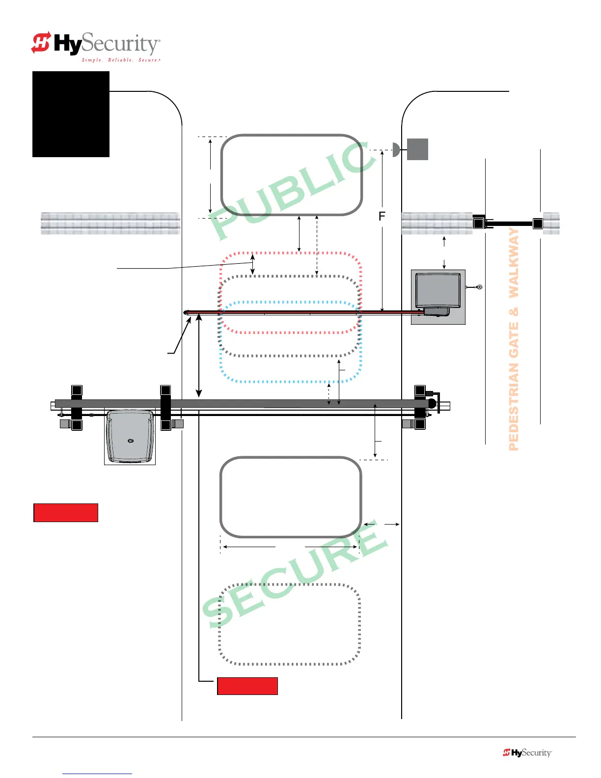
CENTER LOOP
INNER ARMING LOOP
OUTER ARMING LOOP
(OALD)
FREE EXIT LOOP
(optional)
A
B
C
E
F
D
PEDESTRIAN GATE & WALKWAY
C
(IALD)
To sequence the gates, set the
Installer Menu item, SG to “1” in
both gate operators.*
Operator & Loops**
Astrafccontrolandsecuritygates
are separated farther apart, adjust
Center Loop toward centerline of
theTrafcControlGate.
Minimum 2 ft (61 cm)
1
(OALD for both operators)
Loop can be offset from
C/L of barrier arm 1 to 5 ft
(31 to 152 cm)
(IALD for both operators)
IALDforTrafcControlGate
or Free Exit for both operators.
If loop used as Free Exit, you
must have an OALD loop.
TRAFFIC CONTROL GATE
Sequenced Gates #1: Loop Layout
StrongArmPark DC with SlideSmart DC
Drawings not to scale.
*NOTICE
For sequenced gates to operate
properly, all vehicle detectors
must be wired to the Trafc
Control Gate.
If a communication failure occurs,
an AL22 (Alert 22) appears and the
buzzersounds.TheTrafcControl
Gate maintains functionality while-
the Security Gate defaults to open
until communication is restored
(or the Security Gate is manually
closed).
**NOTICE
Center to center between gates:
4 ft minimum (122 cm)
9 ft maximum (274 cm)
Uni- or Bi-directional Trafc Control
Vehicles must pass from one loop to
the next without loss of detection.
Dimension “A” = 6 ft minimum to 12 ft
maximum (183 to 366 cm).
Dimension “B” = 2 ft minimum to 3 ft
maximum (61 to 91 cm).
Dimension“C”=3ftmin.to4ftmax.
DistancefromedgeofCenterLoopto
C/LoftheSecurityGateis3to4ft.
Dimension “D” = 6 ft (183 cm).
Dimension “E” =
4 ft min. to 8 ft (122 to
244 cm)
max.CenterLoopcanbeoffset
fromC/Lofgate:1to5ft(31to152cm).
Dimension “F” =
10to15feet(3to3.6m)
www.hysecurity.com © 2014 Loop Design, Detection, & Layout 7-5
StrongArmParkDC Loop Layout
Optional access control
devices (card reader, etc.).
Align along 6 ft edge of the
Outside Obstruction Loop.
Location changes depending on
uni- or bi-directional trafc.
 Loading...