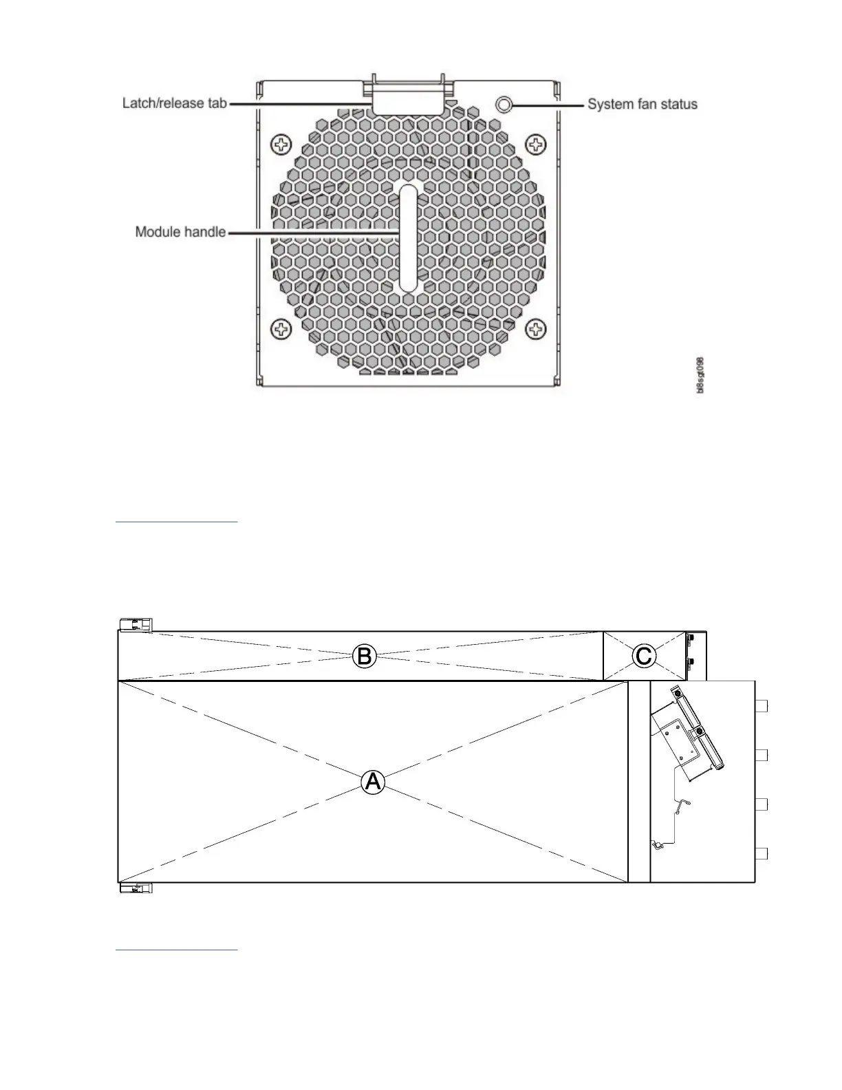
Figure 8. System fan module detail
Enclosure top panel
The enclosure top panel has three different covers, two of which can be removed to provide access to
internal components. Within the illustration, the covers are labeled as A/B/C (see callouts below and
Figure 9 on page 12).
• A: removable lid provides access to HS expanders and disk modules.
• B: removable lid provides access to disk modules, IOM/EBOD expander fan modules, and limited
access to IOMs/EBOD expander modules.
• C: xed cover does not remove. It provides protection for the IOMs/EBOD expander modules.
Figure 9. Model 106 expansion enclosure – top panel with covers installed
Figure 9 on page 12 shows a top view of the enclosure with the covers removed. The illustration is
oriented such that the front of the enclosure is on left, and the rear of the enclosure is on the right. The
enclosure appears as it would if you were observing it on a workbench. The railkit and most of the cable
management arm geometry is omitted for clarity.
12
IBM ESS expansion: Hardware Installation and Maintenance Guide - Model 106