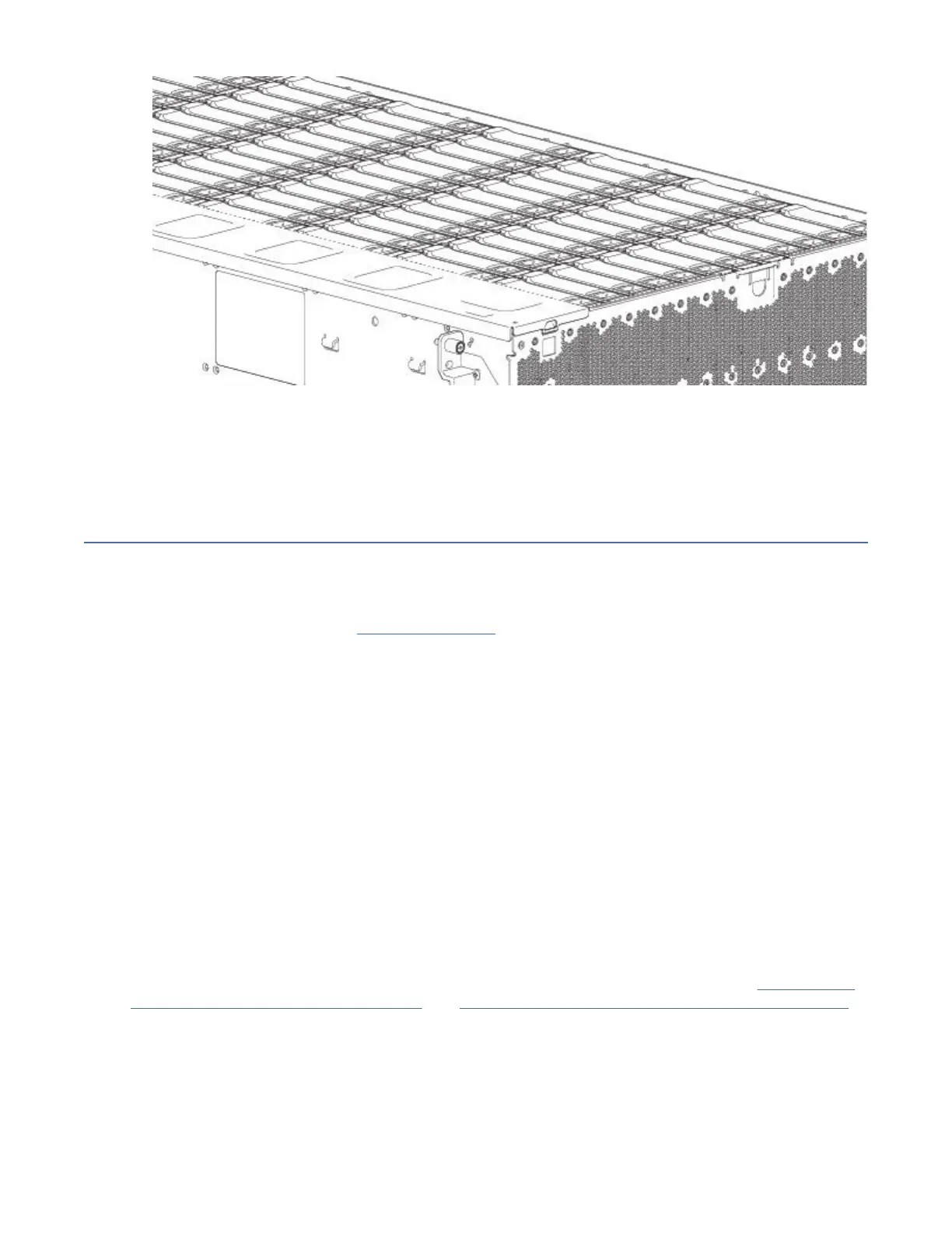
Figure 73. Installing a LFF drive carrier module (2 of 2)
5. Verify that the Amber Fault LED on the disk module handle is off. Verify that the front panel LED states
show no amber module faults. The enclosure front panel Drive Activity LED will blink Green to show
disk activity.
Replacing an IOM/EBOD expander module
Important: If the Model 106 enclosure is congured with a single expansion module, it must be installed
in IOM/EBOD expander module slot No.0. As you face the enclosure rear panel, this is the IOM/EBOD
expander module slot located on the right. An IOM/EBOD expander module blank must be installed in the
adjacent slot (No.1) as shown in Figure 5 on page 10. This conguration is required to ensure sufcient air
flow through the enclosure during operation.
Model 106 only supports dual-IOM/EBOD expander module conguration. The I/O modules are hot-
swappable, which means you can replace one module without halting I/O to declustered array or
powering off the enclosure. In this case, the second module provides paths to the drives until you install
the new module.
You may need to replace an expansion module when:
• The Fault LED is illuminated
• Logs or events in the rmware indicate a problem with the module
• Troubleshooting indicates a problem with the module
Before you begin
Removing an I/O module from an operational enclosure signicantly changes air flow within the
enclosure.
Openings must be populated for the enclosure to cool properly. Leave modules in the enclosure until
ready to install a replacement. If replacing both IOMs/EBOD expander modules in a dual-canister
enclosure, record conguration settings before installing the new controller modules. See “Removing an
IOM/EBOD expander module” on page 79, and “Installing an IOM/EBOD expander module” on page 80
for instructions about installing an additional controller module.
Verifying component failure
• Check Module Fault LED – rear (front of enclosure): Amber= Fault condition.
• Check Fault LED (back of enclosure on IOM/EBOD expander module faceplate): Amber = Fault
condition.
78
IBM ESS expansion: Hardware Installation and Maintenance Guide - Model 106