3. Insert the controller fan module into the slot, and gently press down on the module until it seats rmly
in its connector.
4. Verify that the Controller Fan Status LED is off. Verify that the front panel LED states show no amber
module faults.
5. If replacing multiple fans, repeat steps 1 through 4.
Replacing a HS Expander Module
This section provides procedures for replacing a failed HS Expander module. Illustrations in HS Expander
replacement procedures show top panel views of the enclosure, with the module properly oriented for
insertion into the top panel of the enclosure near the right wall.
If a HS Expander module fails, the remaining modules are sufcient to maintain operation of the
enclosure. You need not halt operations and completely power-off the enclosure when replacing only one
HS Expander module. See CAUTION bullets regarding electrostatic discharge and anti-static protection.
Tip: The illustrations show HS Expander module replacement as you face the enclosure front and view
the top panel. See also Figure 9 on page 12 and Figure 11 on page 13.
Removing a HS Expander module
CAUTION: A hot surface nearby. (L007)
CAUTION: Removing this hot-swappable PCBA disrupts the enclosure’s airflow. Do not remove
the PCBA until you have received the replacement. It is important that all module slots are lled
when the enclosure is in operation.
1. Remove the top lid “A” to access the HS Expander module. See Figure 9 on page 12
.
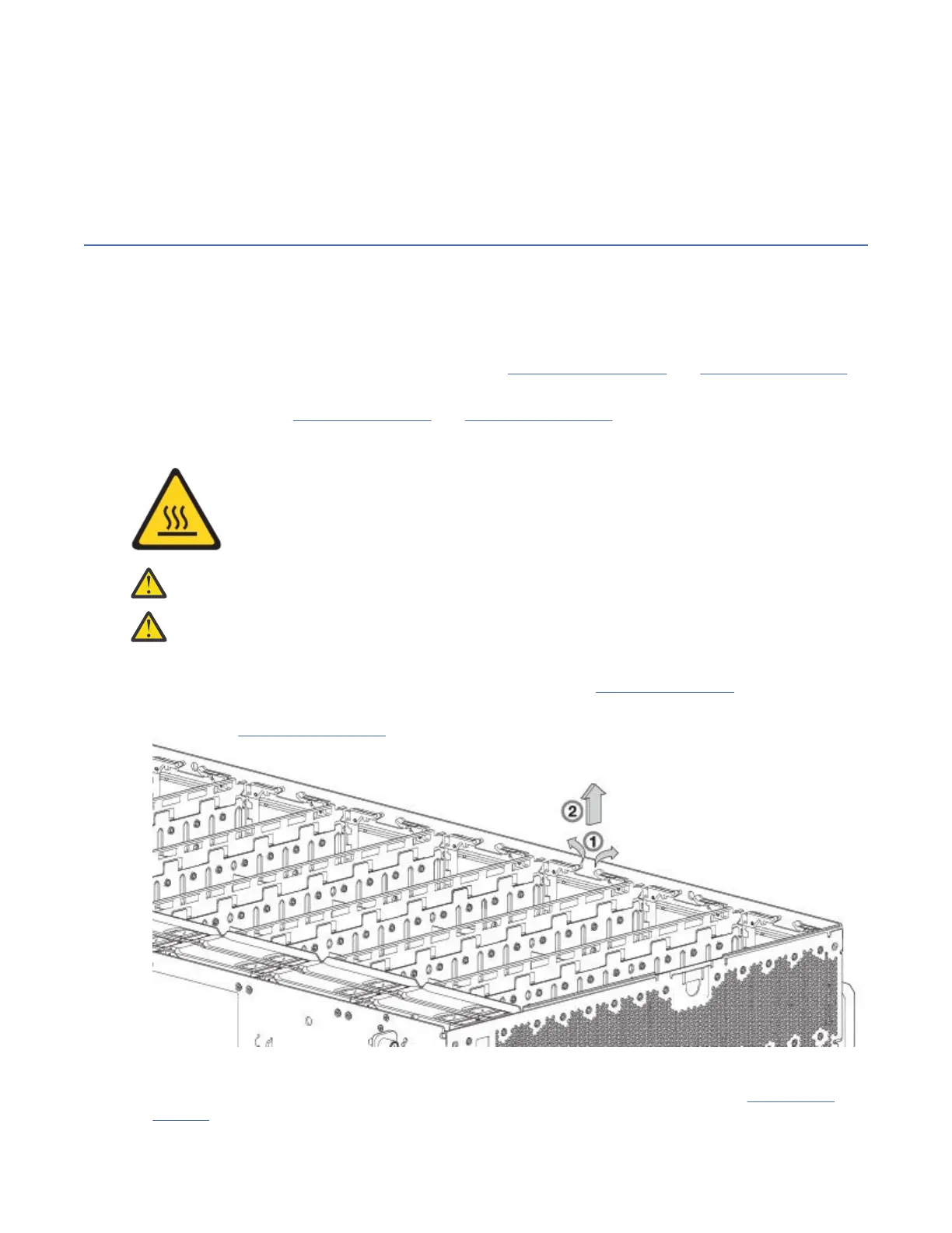
2. On the faulty HS Expander, grasp each of the two plastic swing-arms between thumb and index nger
as shown in Figure 67 on page 74.
Figure 67. Removing a HS Expander (1 of 2)
3. Revolve each swing-arm upward to release the PCBA carrier from its slot as shown in Figure 68 on
page 75.
74
IBM ESS expansion: Hardware Installation and Maintenance Guide - Model 106