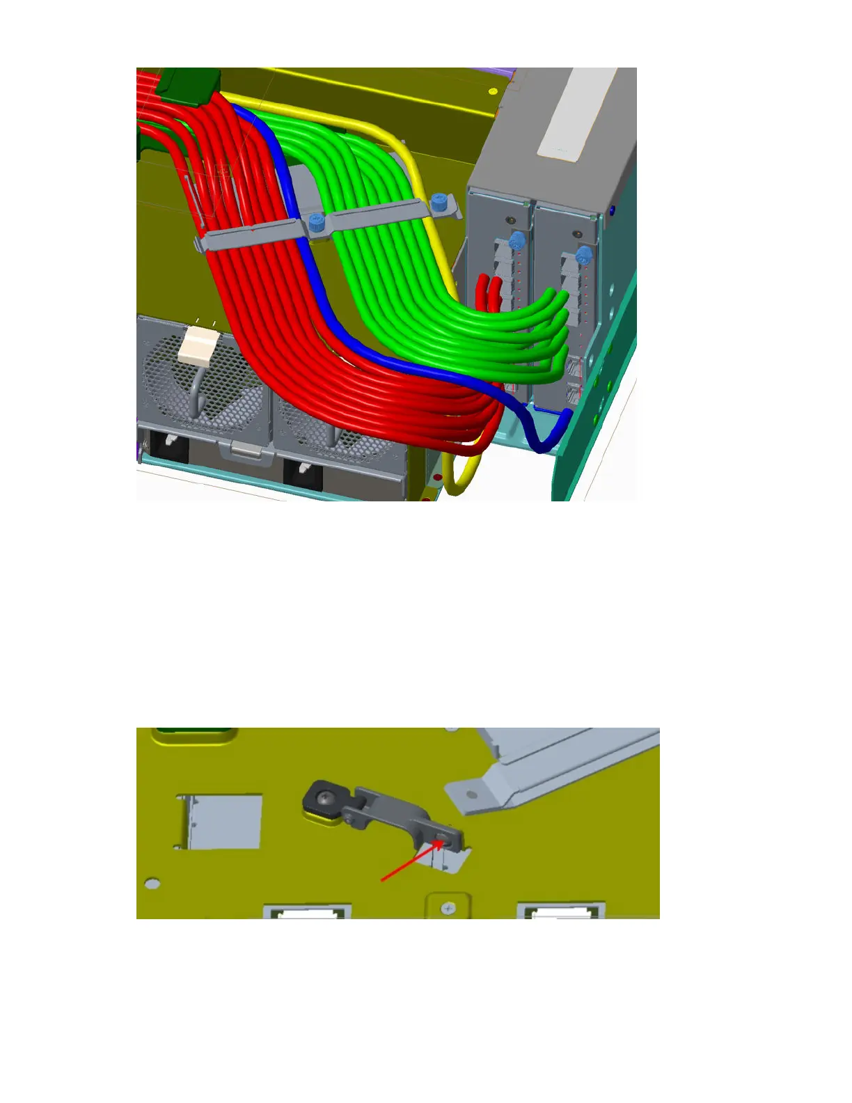
Figure 53. Securing cables with the CMA bracket
3. Install the PSU cables.
Refer to the details provided beneath the sub-steps, noting that the top view details represent the
CMA shelf.
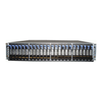
a. Remove the M3 panhead screw from the PSU cable clip assembly, and set it aside for re-
installation.
b. Install the right-angle C19 connectors into the PSUs.
c. Route the cables as shown, ensuring they lay flat on the CMA shelf and through the PSU cable-clip
assembly.
d. Reinstall the M3 panhead screw from step 3a, while torquing the screw to 5 lbf-in.
Figure 54. PSU cable clip M3 panhead screw
48
IBM ESS expansion: Hardware Installation and Maintenance Guide - Model 106