A - Inner CMA arm connector
B - Inner rail connector
C - Outer CMA arm connector
D - Outer rail connector
E - CMA body connector
F - CMA body rail connector
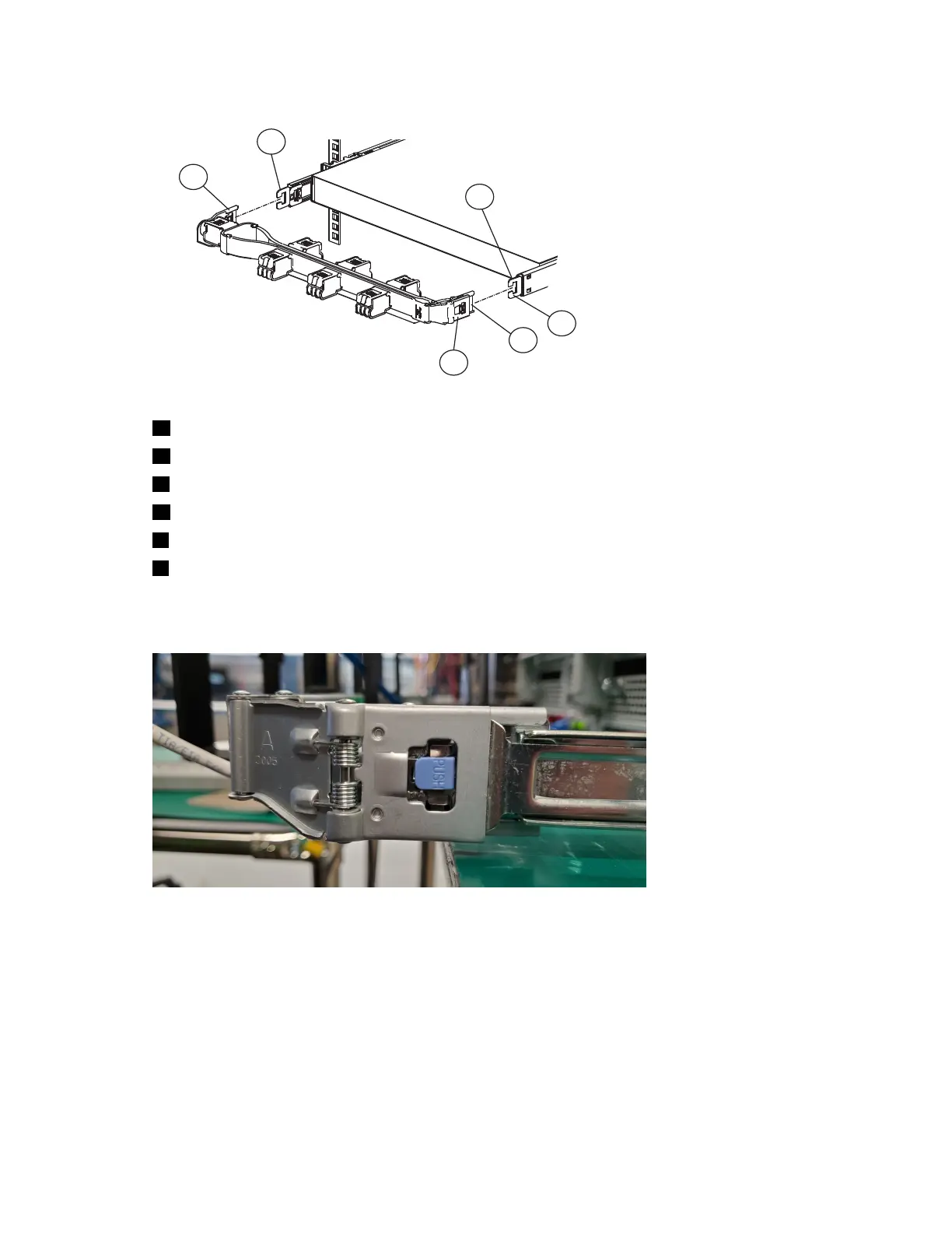
Figure 44. Cable management assembly installation
3. To change the direction of the arm for use on the opposite side of the enclosure, press the release
buttons on the outside of the CMA elbow and rotate the arm 180 degrees.
Figure 45. CMA release buttons
4. Slide the inner CMA arm connector (A) onto the lower right inner rail connector (B) as shown in the
following gure.
Chapter 4. Installing
67
 Loading...