Table 25. Upgrading memory plugging rules. Plug the additional quad of memory modules in any of the
remaining open quad slots
Memory module location CPU socket
P1-C24, P1-C25, P1-C26, P1-C27 P1
P1-C32, P1-C33, P1-C34, P1-C35 P3
P1-C40, P1-C41, P1-C42, P1-C43 P2
P1-C48, P1-C49, P1-C50, P1-C51 P0
Procedure
1. From the Operation list, select Set Identify LED. Then, click OK to conrm the operation.
This action causes causes the blue system ID LED to turn on. You can also identify the locations for the
memory to be installed.
2. Open the rear rack door, if necessary.
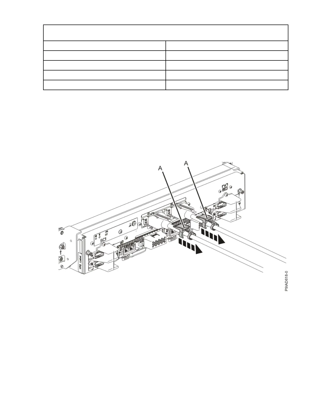
3. Label and disconnect both UPIC cables from the system control unit.
UPIC cable locations are P1-C1-T1 and P1-C2-T1.
a. Remove the white plastic lock (A) from the plug housing.
Figure 168. Removing the UPIC cable lock
b. Push down on the blue cable latch (B) and pull out the UPIC cable from the system control unit.
Memory modules
195

 Loading...