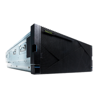
Memory modules
Installing memory modules
Preparing the 9080-M9S system to install memory modules
About this task
The following memory congurations are available for the systems.
• The system nodes use DDR4 memory modules.
• DDR3 memory modules are also supported. Mixing of DDR3 and DDR4 memory modules are not
supported in the same system node.
• For each processor socket, a minimum of 4 of the 8 memory modules must be populated. The only valid
number of memory modules plugged into sites for a given processor module is 4 or 8.
• The memory modules must be plugged in quads (a group of 4). Odd numbers or having 6 memory
modules for a processor is not supported.
• Each memory module within a quad must be the same size and type. The memory module quads can be
different from each other.
• To ensure proper cooling, a memory module or a memory module ller is required in all locations.
• Table 8 on page 103 shows the base memory plugging rules.
• Table 9 on page 103 shows the plugging rules for adding memory. Quads must be added next to a
processor. The quads can be added in any order.
Table 8. Base memory plugging rules
Memory module location CPU socket
P1-C22, P1-C23, P1-C28, P1-C29 P1
P1-C30, P1-C31, P1-C36, P1-C37 P3
P1-C38, P1-C39, P1-C44, P1-C45 P2
P1-C46, P1-C47, P1-C52, P1-C53 P0
Table 9. Upgrading memory plugging rules. Plug the additional quad of memory modules in any of the
remaining open quad slots
Memory module location CPU socket
P1-C24, P1-C25, P1-C26, P1-C27 P1
P1-C32, P1-C33, P1-C34, P1-C35 P3
P1-C40, P1-C41, P1-C42, P1-C43 P2
P1-C48, P1-C49, P1-C50, P1-C51 P0
Procedure
1. From the Operation list, select Set Identify LED. Then, click OK to conrm the operation.
This action causes causes the blue system ID LED to turn on. You can also identify the locations for the
memory to be installed.

 Loading...