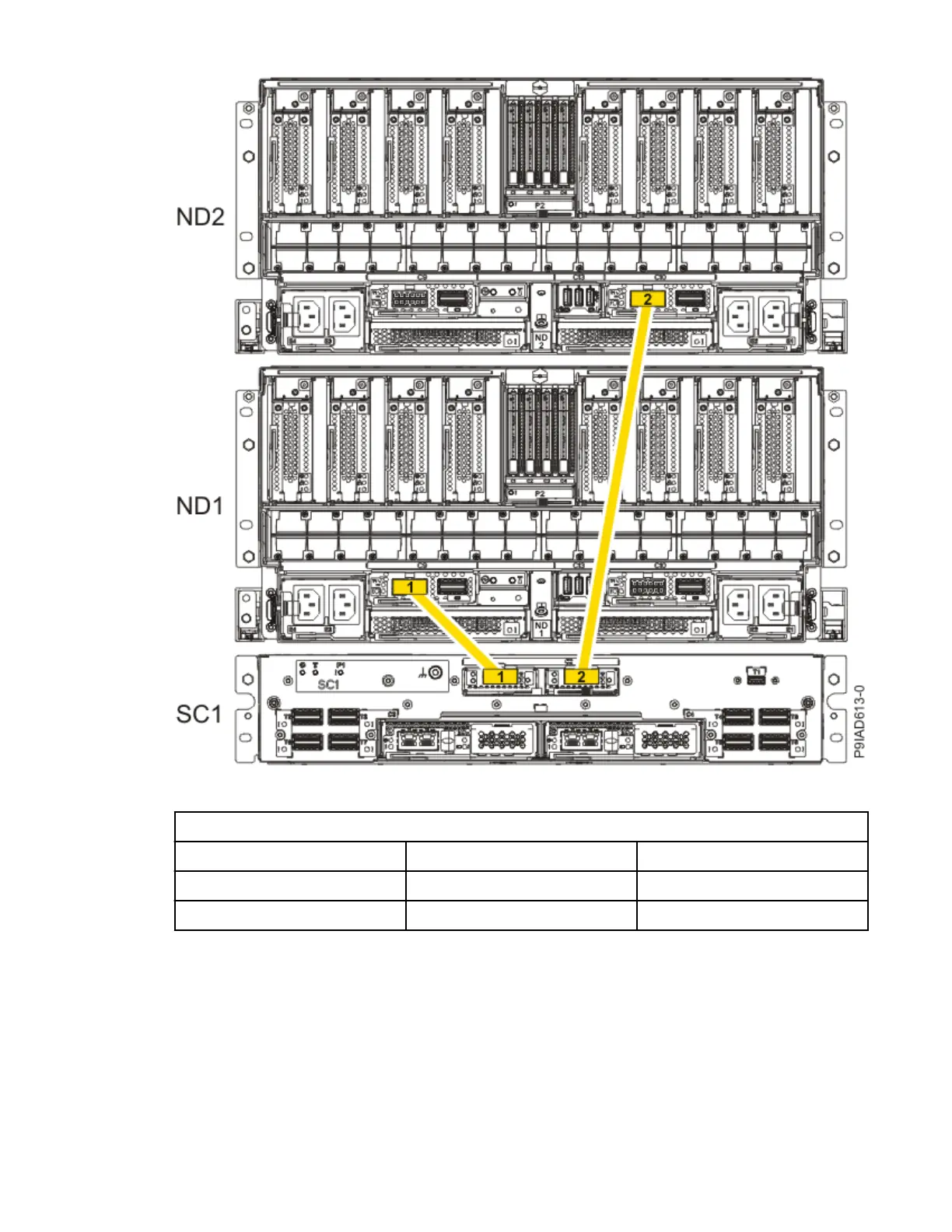
Figure 44. Two, Three, or Four Node Conguration UPIC Cabling
Table 6. Two, Three, or Four Node
Conguration UPIC Cabling
Cable From To
1 SC1: P1-C1-T1 ND1: P1-C9-T1
2 SC1: P1-C2-T1 ND2: P1-C10-T1
3. To replace the UPIC cable in the system node, complete the following steps:
a. Ensure that the white plastic lock is pulled back from the plug housing.
b. Plug the UPIC cable (A) into the previously identied location in the system node by inserting the
cable into the connector until it locks into place, as shown in the following gure.
Cables
51

 Loading...