Table 7. USB Cabling
From To
ND1 or ND2: P1-C13-T3 SC1: P1-T1
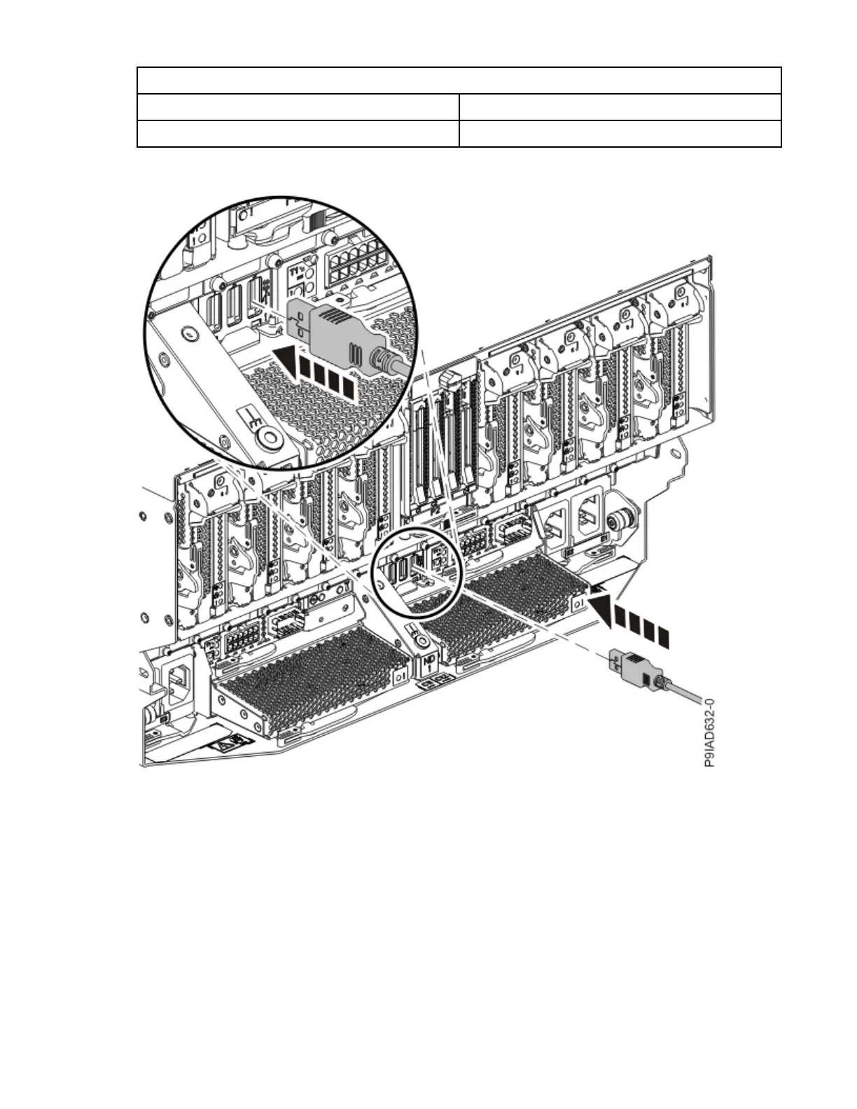
3. Plug the USB cable into the previously identied location in the system node by inserting the cable into
the connector, as shown in the following gure.
Figure 54. Replacing the USB cable into the system node
4. Plug the USB cable into the previously identied location in the system control unit by inserting the
cable into the connector, as shown in the following gure.
60
Power Systems: Removing and replacing parts in the 9080-M9S system

 Loading...