190 IBM eX5 Implementation Guide
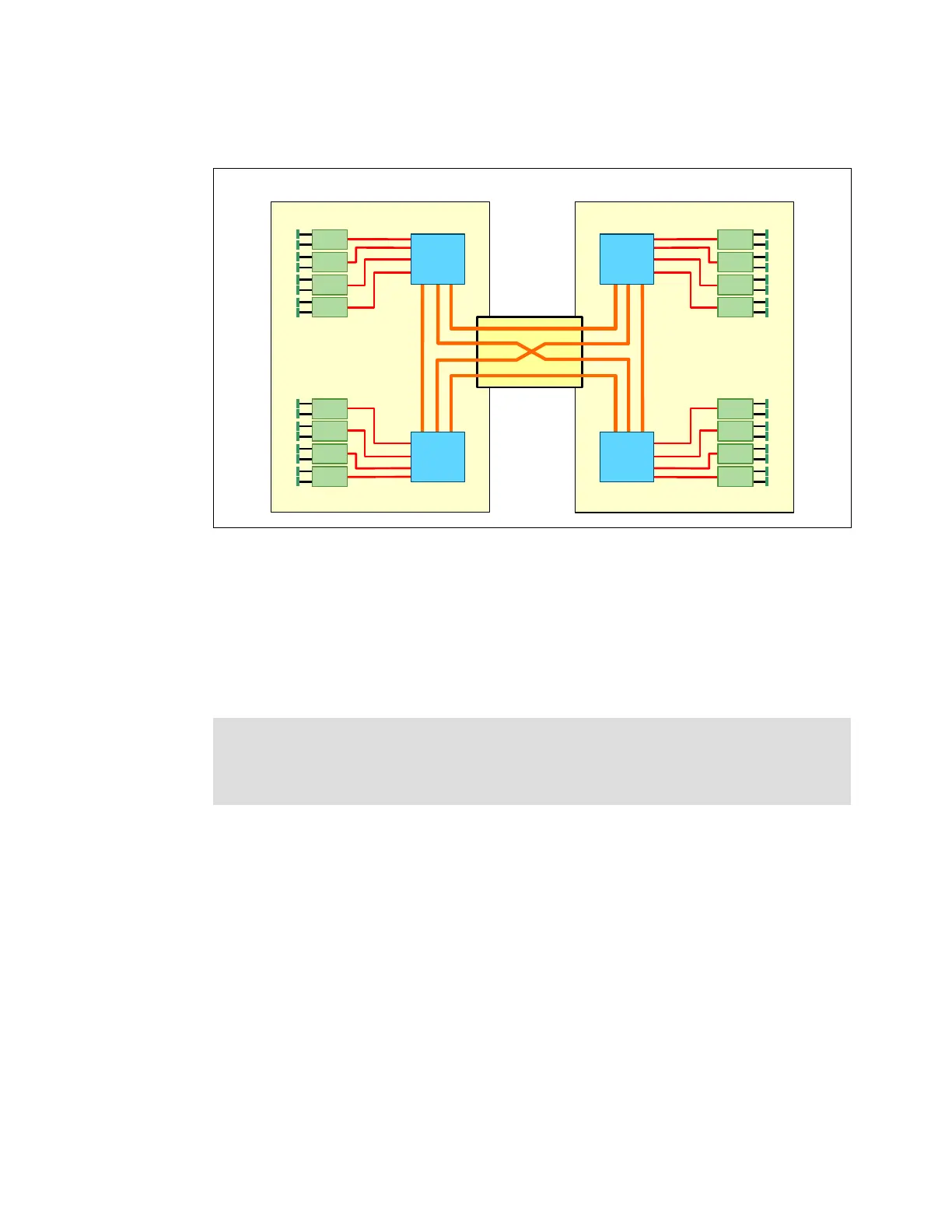
Figure 5-9 shows the block diagram of a 2-node HX5 and the location of the HX5 2-node
scalability card.
Figure 5-9 Block diagram of a 2-node HX5
Ensure that all firmware is up-to-date before attaching the blades together. For the minimum
firmware requirements, see 8.2.3, “Required firmware of each blade and the AMM” on
page 379.
For configuring software when using a 2-node for creating the partition in a scalable complex,
using Flexnode to toggle between a single blade and a 2-node, and deleting the partition, see
8.6, “Creating an HX5 scalable complex” on page 402.
5.8.3 HX5 with MAX5
In the HX5 and MAX5 configuration, the HX5 and MAX5 units connect through a 1-node
MAX5 scalability card, which provides QPI scaling. See Figure 5-10 on page 191.
Important: When a blade is attached, it does not automatically become a 2-node
single-image system. You must create the 2-node single-image system by using the
scalable complex in the Advanced Management Module (AMM) in the chassis. See 8.6,
“Creating an HX5 scalable complex” on page 402 for more information.
HX5
2-node
scalability kit
HX5
QPI
links
SMI
links
SMI
links
16 DIMMs
(1 DPC)
QPI
links
SMI
links
SMI
links
16 DIMMs
(1 DPC)
CPU
1
CPU
2
CPU
1
CPU
2
HX5
 Loading...