66 IBM eX5 Implementation Guide
3.4 System architecture
This section explains the system board architecture and the use of the QPI wrap card.
3.4.1 System board
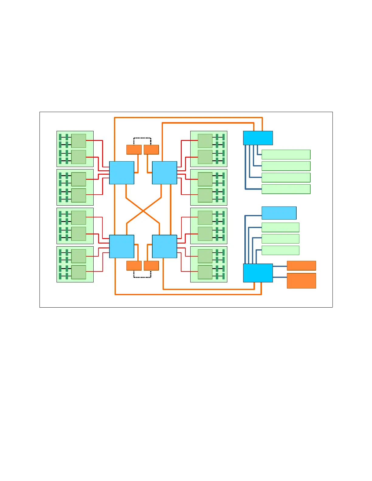
Figure 3-7 shows the system board layout of a single-node 4-way system.
Figure 3-7 Block diagram for single-node x3850 X5
In Figure 3-7, the dotted lines indicate where the QPI Wrap Cards are installed in a
4-processor configuration. These wrap cards complete the full QPI mesh to allow all four
processors to connect to each other. The QPI Wrap Cards are not needed in 2-processor
configurations and are removed when a MAX5 is connected.
Figure 3-12 on page 70 is a block diagram of the x3850 X5 connected to a MAX5.
3.4.2 QPI Wrap Card
In the x3850 X5, QPI links are used for interprocessor communication, both in a single-node
system and in a 2-node system. They are also used to connect the system to a MAX5
memory expansion drawer. In a single-node x3850 X5, the QPI links connect in a full mesh
between all CPUs. To complete this mesh, the QPI Wrap Card is used.
SMI
links
MB 2
MB 1
MB 2
MB 1
MB 2
MB 1
MB 2
MB 1
Memory card 5Memory card 6
Memory card 1
Memory card 2
QPI
links
Intel
Xeon
CPU 3
Intel
Xeon
CPU 1
MB 2
MB 1
MB 2
MB 1
MB 2
MB 1
MB 2
MB 1
Memory card 7Memory card 8
Memory card 3
Memory card 4
QPI
ports
Intel
Xeon
CPU 4
Intel
Xeon
CPU 2
Intel
I/O Hub
QPI
links
Slot 1: x16 FL
Slot 2: x4 FL*
Slot 3: x8 FL
Slot 4: x8 FL
Slot 5: x8 HL
Slot 6: x8 HL
Slot 7: x8 HL†
Intel
I/O Hub
† Slot 7 keyed for the
10Gb Ethernet adapter
Intel
Southbridge
Dual Gb
Ethernet
x4
DVD, USB,
IMM, LP
SAS
x8
* x8 mechanical
QPI QPI
QPI QPI
QPI
ports
 Loading...