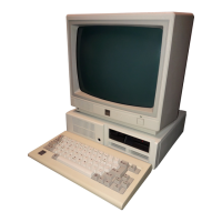
MAP 2400 (continued)
1
5
11
15
6
10
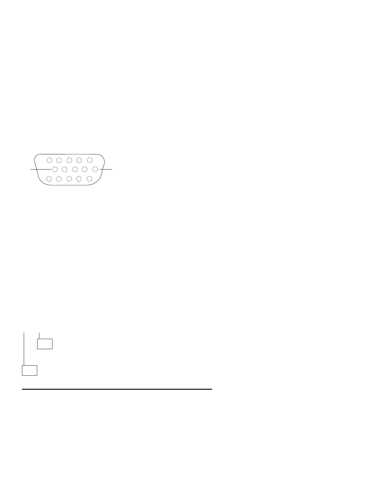
Figure 2-15. Display Connector
ARE THE VOLTAGES CORRECT?
Yes No
107
Replace the system board.
108
Replace the display. If the symptom remains, replace the system board.
1. Press 7; then press Enter and check for:
0 to +0.2 V dc from pin 13 to 10 (ground)
0 to +0.2 V dc from pin 14 to 10 (ground)
2. Press Enter; then check for:
+3.5 to +4.5 V dc from pin 13 to 10 (ground)
0 to +0.2 V dc from pin 14 to 10 (ground)
3. Press Enter; then check for:
0 to +0.2 V dc from pin 13 to 10 (ground)
0 to +0.2 V dc from pin 14 to 10 (ground)
4. Press Enter; then check for:
+0.5 to 1.0 V dc from pin 13 to 10 (ground)
+3.5 to 4.5 V dc from pin 14 to 10 (ground)
2-118