Connectors, LEDs, and jumpers
The following illustrations show the connectors, light-emitting diodes (LEDs), and
jumpers on the system board. The illustrations might differ slightly from your
hardware.
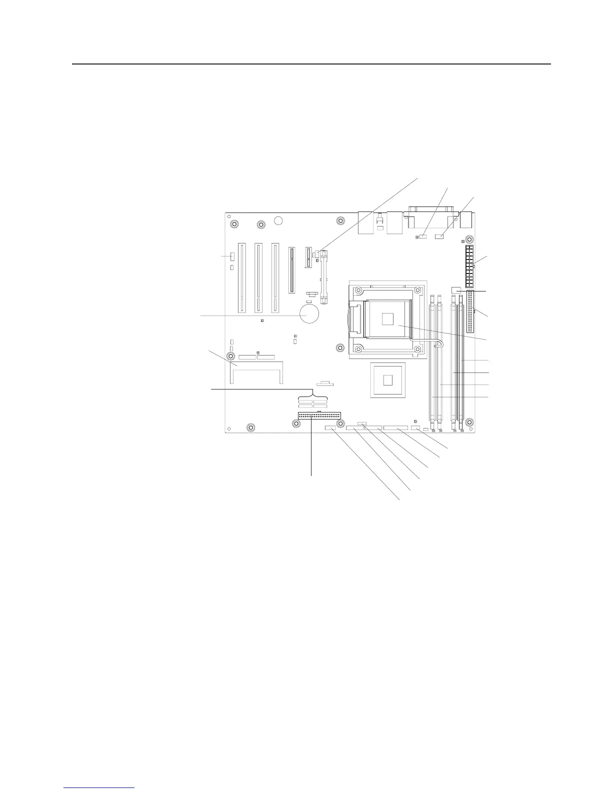
System-board internal connectors
The following illustration shows the internal connectors on the system board.
Rear system fan connector
Microprocessor fan
Serial 2 connector
Power connector
(24 pin)
Power connector
(4 pin)
Drive connector
(optional)
Hard disk drive fan connector
Hard disk drive backplane connector
Microprocessor
connector
DIMM 1 connector
DIMM 2 connector
DIMM 3 connector
DIMM 4 connector
Front panel connector
Front USB connector
mini-BMC JTAG connector
USB tape drive connector
IDE connector
SATA drive
connectors (4)
SAS/SATA
controller
connector
Wake-on-LAN
Battery
Chapter 1. Introduction 9