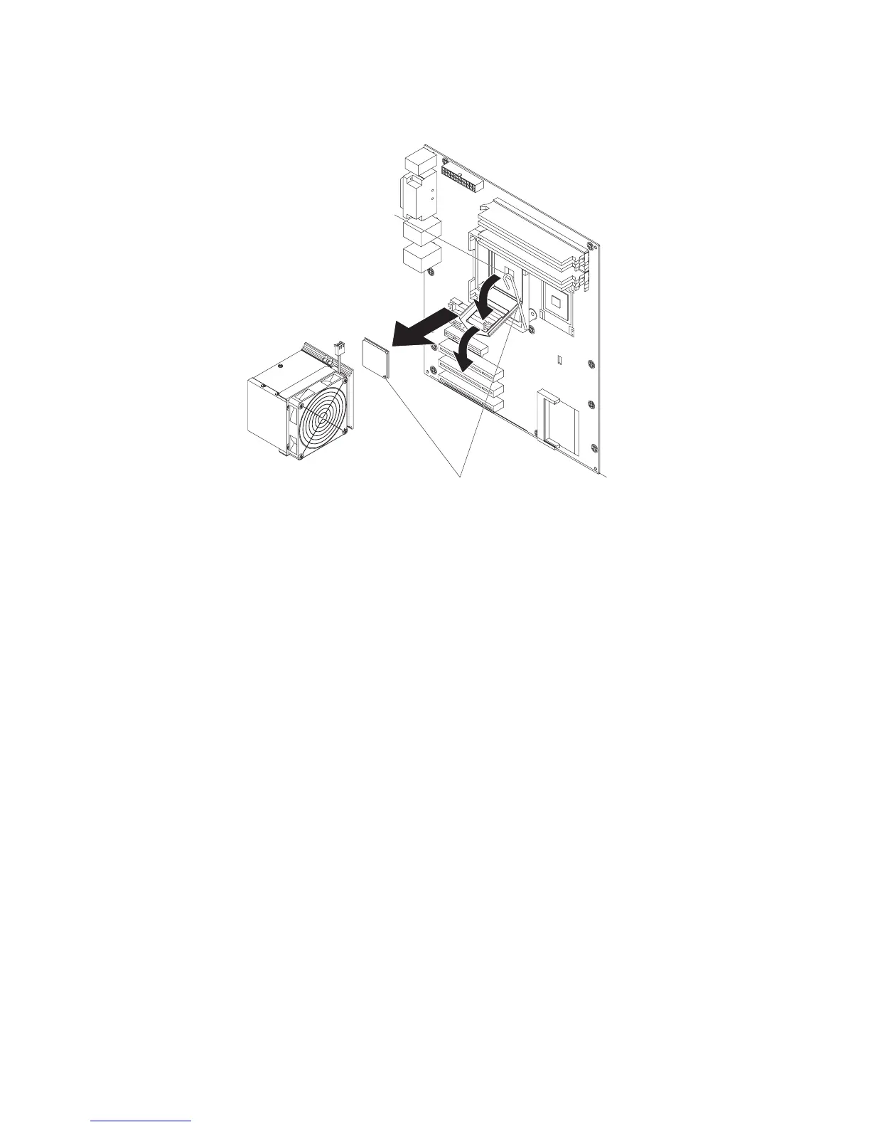
Removing the microprocessor and fan sink
To remove the microprocessor and fan sink, complete the following steps.
Orientation indicators
Fan-sink retention lever
1. Read the safety information that begins on page vii and “Installation guidelines”
on page 73.
2. Turn off the server and all attached devices; then, disconnect all power cords
and external cables.
3. Turn the server on its side so that it is lying flat, with the cover facing up.
4. Unlock and remove the side cover (see “Removing the side cover” on page
77).
5. Disconnect any cables that impede access to the fan sink and microprocessor.
Attention: The fan-sink retention lever is spring-loaded when the fan sink is
in place. Releasing the lever too quickly or allowing it to spring upward can
damage the fan sink and surrounding components.
6. Remove the fan sink from the microprocessor:
a. Disconnect the fan-sink cable from the system board.
b. Release the fan-sink retention lever by pressing down on the end, moving
it to the side and slowly releasing it to the open (up) position.
Important: Be careful when you handle the microprocessor and fan sink.
If the microprocessor and fan sink will be reused, do not contaminate the
thermal material between them.
c. Tip the top of the fan sink toward the front of the server while you slide it
away from the lower flange of the retention module; then, remove it from
the server. After removal, place the fan sink on its side on a clean, flat
surface.
Attention: The microprocessor retention latch is spring-loaded when the
microprocessor is in place. Releasing the latch too quickly or allowing it to
spring upward can damage the microprocessor and surrounding components.
7. Release the microprocessor retention latch by pressing down on the end,
moving it to the side, and slowly releasing it to the open (up) position.
Chapter 4. Removing and replacing server components 123