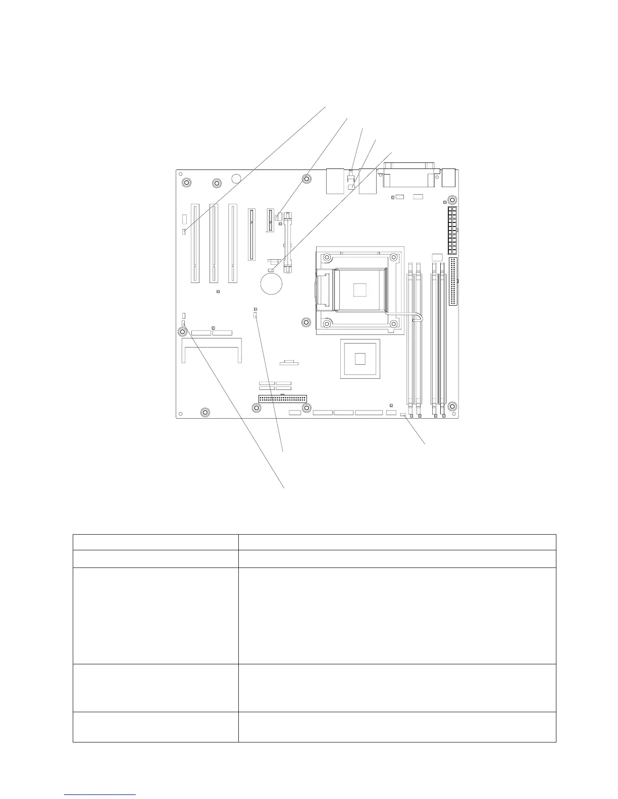
System-board jumpers
The following illustration shows the jumpers on the system board.
NMI button
NMI button switch (SW1)
Serial 2 switch (JP9)
System rest (nopop) (JP3)
Boot block jumper (JP6)
Clear CMOS jumper (JP 2)
mini-BMC force update jumper (JP 1)
Force power on jumper(JP8)
The following table describes the function of each jumper block.
Table 2. System-board jumper blocks
Jumper name Description
Mini-BMC force update (JP1) Pins 1 and 2: Normal (default)
Clear CMOS (JP2)
v Pins 1 and 2: Keep CMOS data (default)
v Pins 2 and 3: Clear the CMOS data, which clears the power-on
password
Note: Changing the position of this jumper does not affect the
administrator password check if an administrator password is set.
If the administrator password is set and forgotten, remove and
then reinstall the battery.
Boot block (JP6)
v Pins 1 and 2: Normal (default)
v Pins 2 and 3: Recover boot block (see “Recovering from a BIOS
update failure” on page 53)
Force power-on (JP8) Pins 1 and 2: Use the power-control button to start the server
(default)
Chapter 1. Introduction 13