POST beep codes
A beep code is a combination of short or long beeps or series of short beeps that
are separated by pauses. For example, a “1-2-3” beep code is one short beep, a
pause, two short beeps, and pause, and three short beeps. A beep code indicates
that POST has detected a problem.
The following table describes the beep codes and suggested actions to correct the
detected problems.
A single problem might cause more than one error message. When this occurs,
correct the cause of the first error message. The other error messages usually will
not occur the next time POST runs.
Exception: If there are multiple error codes that indicate a microprocessor error,
the error might be in a microprocessor or in a microprocessor socket. See
“Microprocessor problems” on page 35 for information about diagnosing
microprocessor problems.
v Follow the suggested actions in the order in which they are listed in the Action column until the problem
is solved.
v See Chapter 3, “Parts listing, System x3200 Types 4362 and 4363,” on page 67 to determine which
components are customer replaceable units (CRU) and which components are field replaceable units
(FRU).
v If an action step is preceded by “(Trained service technician only),” that step must be performed only by a
trained service technician.
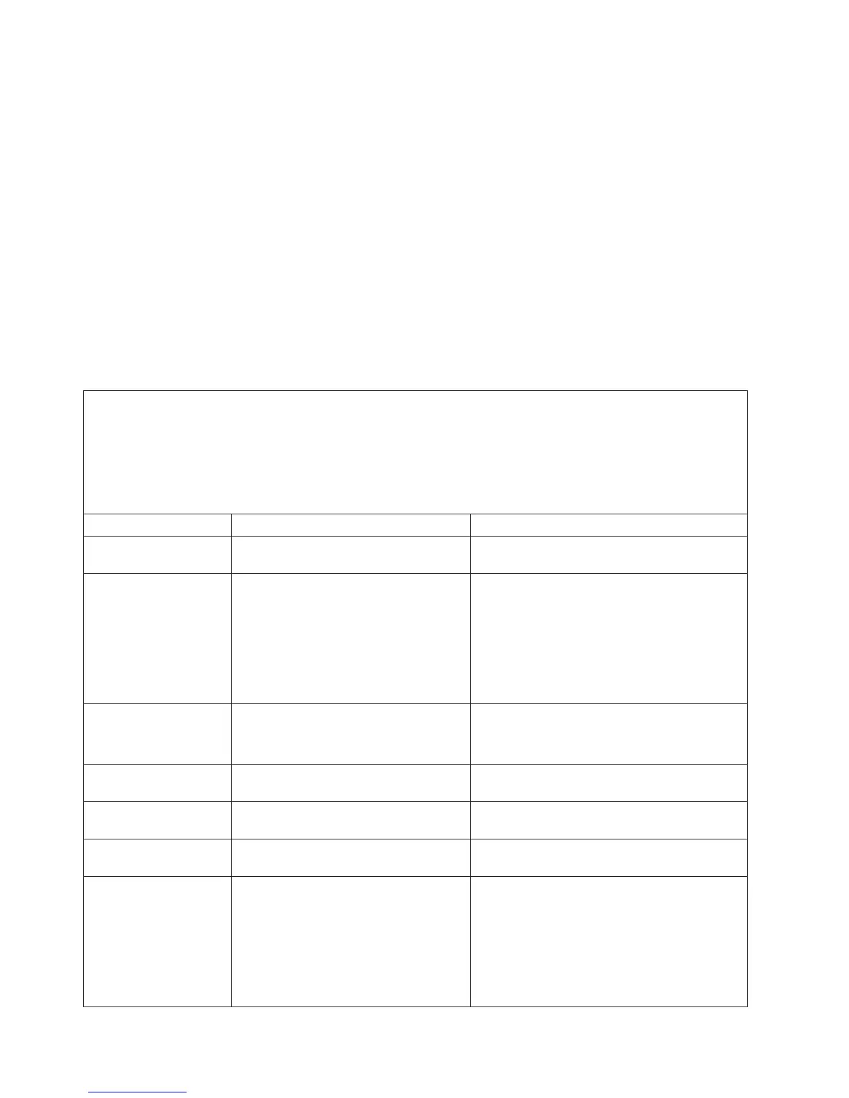
Beep code Description Action
One short beep Indicates successful completion of
POST, with no errors.
None
1-1-3 CMOS write/read test failed.
1. Reseat the battery.
2. Replace the following components one at a
time, in the order shown, restarting the
server each time:
a. Battery
b. (Trained service technician only) System
board
1-1-4 BIOS ROM checksum failed.
1. Recover the BIOS code.
2. (Trained service technician only) Replace
the system board.
1-2-1 Programmable interval timer failed. (Trained service technician only) Replace the
system board.
1-2-2 DMA initialization failed. (Trained service technician only) Replace the
system board.
1-2-3 DMA page register write/read failed. (Trained service technician only) Replace the
system board.
1-2-4 RAM refresh verification failed.
1. Reseat the DIMMs.
2. Replace the following components one at a
time, in the order shown, restarting the
server each time:
a. DIMMs
b. (Trained service technician only) System
board
16 System x3200 Types 4362 and 4363: Problem Determination and Service Guide