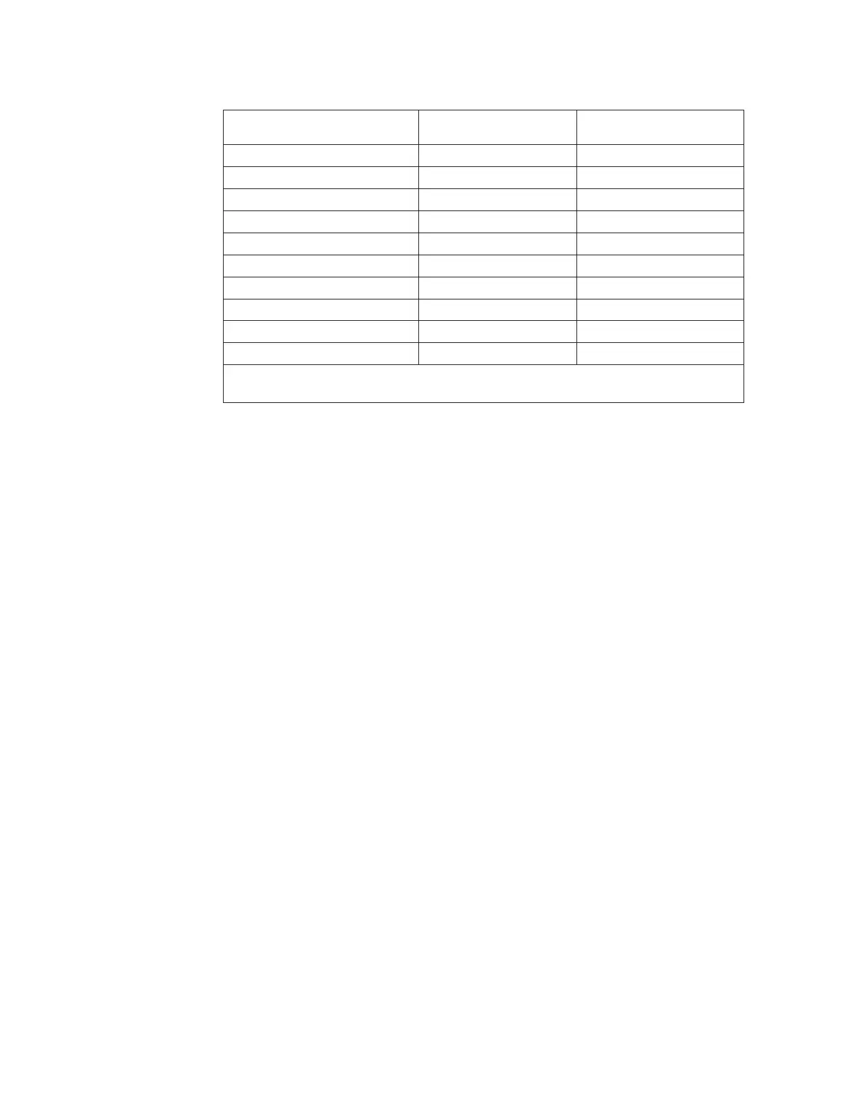
Table 23. Memory rank sparing mode DIMM population sequence (continued)
Number of DIMMs
Number of installed
microprocessor DIMM connector
Third pair of DIMMs 1 8, 9
Fourth pair of DIMMs 1 11, 12
Fifth pair of DIMMs 1 7, 10
Sixth pair of DIMMs 1 3, 6
Seventh pair of DIMMs 2 13, 14
Eighth pair of DIMMs 2 16, 17
Ninth pair of DIMMs 2 20, 21
Tenth pair of DIMMs 2 23, 24
Eleventh pair of DIMMs 2 19, 22
Twelfth pair of DIMMs 2 15, 18
Table note: DIMM connectors 3, 6, 7, 10, 15, 18, 19, and 22 are not used in memory rank
sparing mode when UDIMMs are installed in the server.
Replacing a memory module:
Use this information to install a memory module.
About this task
To install a memory module, complete the following steps:
Procedure
1. Read the safety information that begins on “Safety” on page vii and
“Installation guidelines” on page 33.
2. Turn off the server and peripheral devices and disconnect the power cords
and all external cables, if necessary.
3. Remove the cover (see “Removing the cover” on page 36).
4. Remove the air baffle (see “Removing the air baffle” on page 37).
5. Carefully open the retaining clips on each end of the DIMM connector and
remove the DIMM.
Attention: To avoid breaking the retaining clips or damaging the DIMM
connectors, open and close the clips gently.
242 IBM System x3550 M4 Type 7914: Installation and Service Guide
 Loading...


