2
PANEL DESCRIPTION
2-5
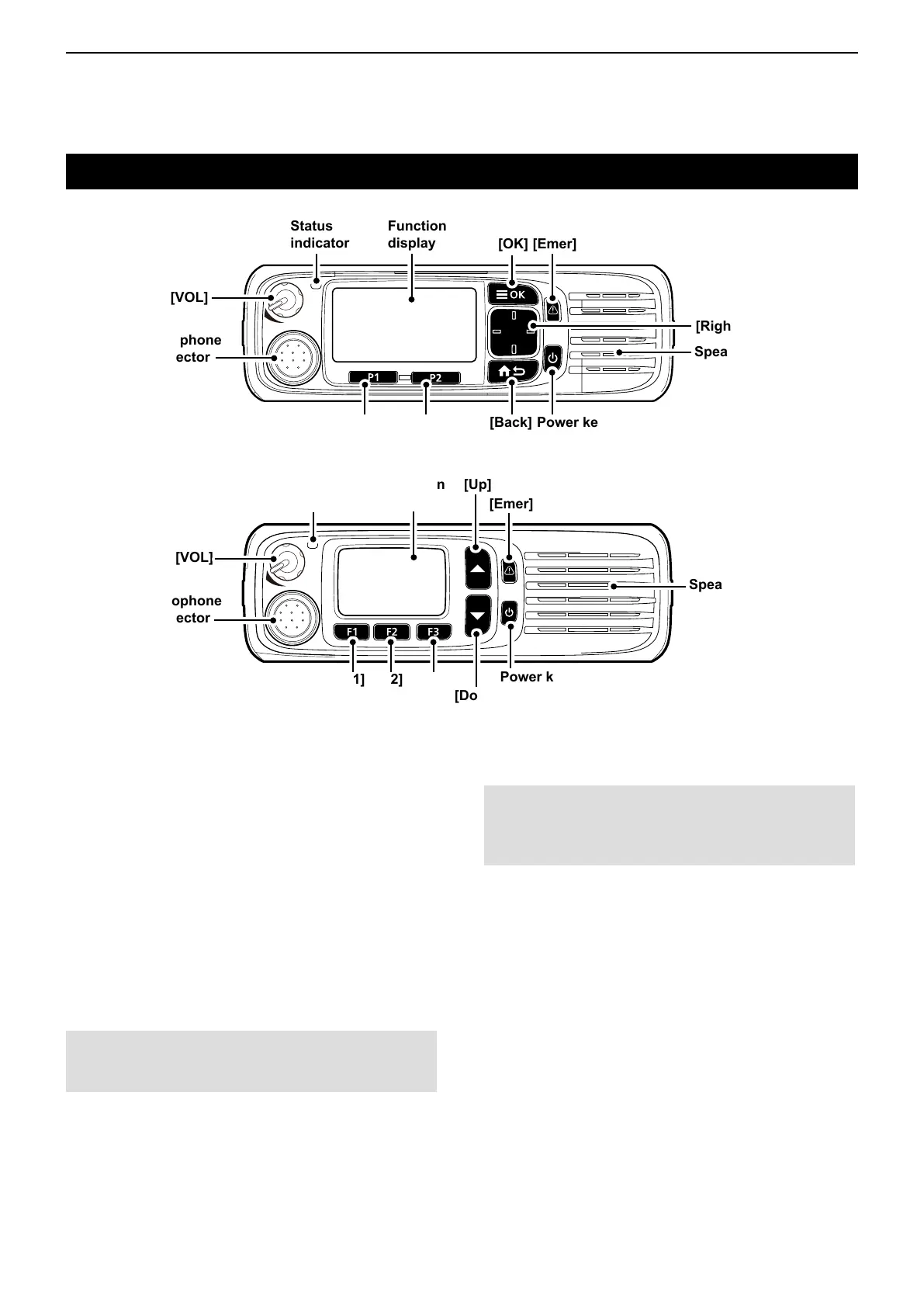
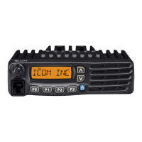
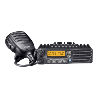
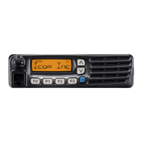
Front, top and side panels (for the Mobile type transceiver)
D About the transceiver types
There are 2 types of transceivers in the IC-F5400D
and IC-F6400D series.
IC-F5400D, IC-F6400D: LCD types
IC-F5400DS, IC-F6400DS: Segment types
D About the Status indicator
• Lights red while transmitting.
• Lights green while receiving a signal, or when the
squelch is open.
D About the Microphone connector
Connect the supplied or optional microphone.
CAUTION: DO NOT
connect non-specied
microphones. The pin assignments may be different
and may damage the transceiver.
Speaker
[VOL]
Status
indicator
Microphone
connector
Function
display
[OK]
[Emer]
[Up]/[Down]
[Right]/[Left]
[Back]
[P1] [P2]
Power key
F1 F2 F3
[VOL]
Microphone
connector
Function
display
[Emer]
Power key
Speaker
[Up]
[Down]
[F1] [F2] [F3]
Status
indicator
z LCD type
z Segment type
D About the Software key functions
NOTE: Dealers can assign the Software key
functions to the keys and keypads, except for the
Power key.
LSee page 2-13 for details.